zone to trip after the
tCoord
timer has elapsed. The
tCoord
in permissive
underreaching schemes is normally set to zero.
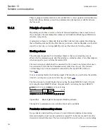
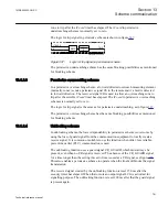
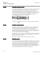
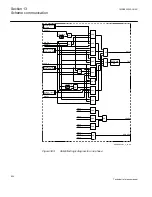
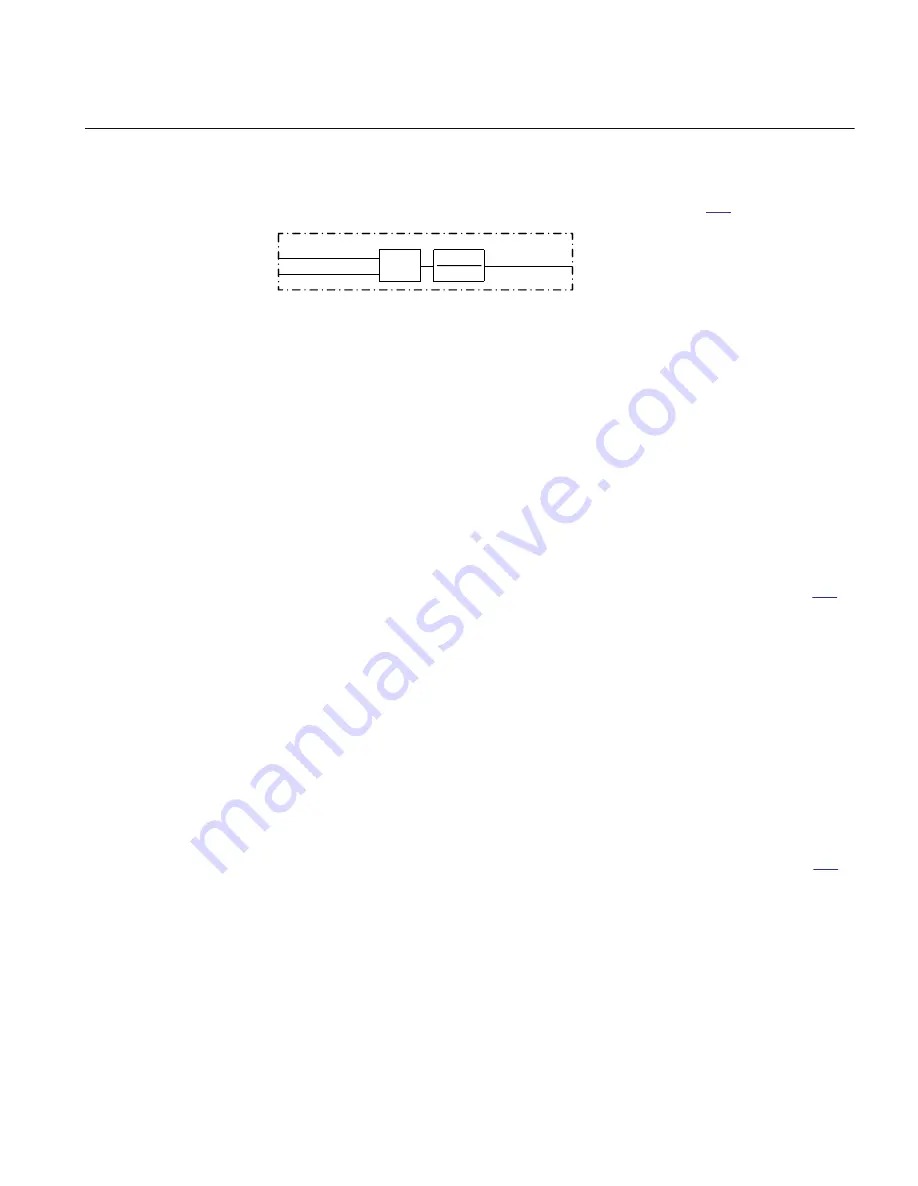
The logic for trip signal in permissive scheme is shown in figure
PLTR-CRD
CR
TRIP
AND
en05000513_ansi.vsd
0-tCoord
0
ANSI05000513 V1 EN
Figure 387:
Logic for trip signal in permissive scheme
The permissive underreaching scheme has the same blocking possibilities as mentioned
for blocking scheme.
13.1.2.3
Permissive overreaching scheme
In a permissive overreaching scheme, a forward directed overreach measuring element
(normally zone2) sends a permissive signal CS to the remote end if a fault is detected
in forward direction. The received signal CR is used to allow an overreaching zone to
trip after the settable
tCoord
timer has elapsed. The
tCoord
in permissive overreaching
schemes is normally set to zero.
The logic for trip signal is the same as for permissive underreaching, as in figure
.
The permissive overreaching scheme has the same blocking possibilities as mentioned
for blocking scheme.
13.1.2.4
Unblocking scheme
In unblocking scheme, the lower dependability in permissive scheme is overcome by
using the loss of guard signal from the communication equipment to locally create a
receive signal. It is common or suitable to use the function when older, less reliable,
power-line carrier (PLC) communication is used.
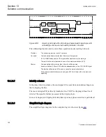
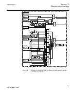
The unblocking function uses a guard signal CR_GUARD, which must always be
present, even when no CR signal is received. The absence of the CR_GUARD signal
for a time longer than the setting
tSecurity
time is used as a CR signal, see figure
.
This also enables a permissive scheme to operate when the line fault blocks the signal
transmission.
The received signal created by the unblocking function is reset 150 ms after the
security timer has elapsed. When that occurs an output signal LCG is activated for
signalling purpose. The unblocking function is reset 200 ms after that the guard signal
is present again.
1MRK505222-UUS C
Section 13
Scheme communication
791
Technical reference manual
Summary of Contents for Relion 670 series
Page 1: ...Relion 670 series Line differential protection RED670 ANSI Technical reference manual...
Page 2: ......
Page 40: ...34...
Page 50: ...44...
Page 60: ...54...
Page 126: ...120...
Page 384: ...378...
Page 496: ...490...
Page 556: ...550...
Page 602: ...596...
Page 620: ...614...
Page 794: ...788...
Page 864: ...858...
Page 988: ...982...
Page 998: ...992...
Page 1084: ...1078...
Page 1164: ...1158...
Page 1168: ...1162...
Page 1220: ...1214...
Page 1230: ...1224...
Page 1231: ...1225...

