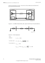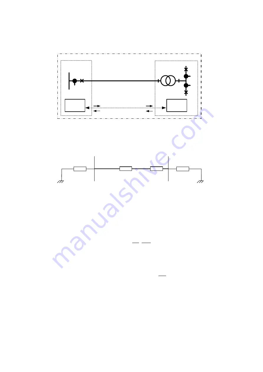
Both terminals operate as masters. If at least one of them indicates an internal fault, the
protected circuit is disconnected.
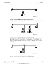
IED 2
Line 50 km
CT 3
Substation 2
Substation 1
Current samples from terminals 2 and 3
Current samples from terminal 1
CT 2
Yd1
200 MVA,
220 / 70 kV,
525 / 1650 A
Y
d
220 kV, 600 A
CB 1
te
rm
in
a
l 2
t
e
rm
in
a
l 3
CB 2
CB 3
te
rm
in
a
l 1
CT 1
IED 1
IEC05000534-2-en.vsdx
IEC05000534 V2 EN-US
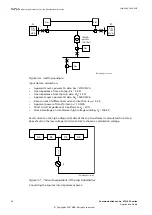
Figure 34: Line differential protection with a power transformer in the protected zone
Z
L
Z
T
Zsource 2/3
Zsource 1
IEC05000444-2-en.vsdx
IEC05000444 V2 EN-US
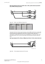
Figure 35: Circuit impedances
where:
Line data is
15.0
L
L
Z
X
»
=
W
EQUATION1419 V1 EN-US
Transformer data is
2
220
10 220
% 10%
24.2
100 200
T
X
X
=
Þ
=
×
=
W
EQUATION1420 V1 EN-US
Source impedance is
1
7.0
Source
Z
=
W
EQUATION1421 V1 EN-US
2
Source2 / 3
Source2 / 3 220
220
Z
5
(Z
)
5 49.4
70
= W Þ
=
× =
W
æ
ö
ç
÷
è
ø
EQUATION1422 V1 EN-US
Section 4
1MRK 505 382-UEN E
Analog and binary signal transfer for line differential protection
32
Communication set-up, 670/650 series
Application Guide
© Copyright 2017 ABB. All rights reserved
Summary of Contents for Relion 670 series
Page 1: ...Relion 670 650 SERIES Communication set up 670 650 series Version 2 2 Application Guide...
Page 2: ......
Page 10: ...4...
Page 99: ...93...


