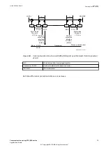
cable. The outer shield around the cable consists of a braided mesh. In addition, every twisted
pair has a foil shielding.
If you use an S7FTP patch cable for ethernet, be aware that a cross-connected cable has only
pairs on pin 1-2 and 3-6 cross-connected. The two remaining pairs are not cross-connected.
Clock configuration switch
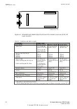
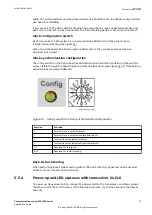
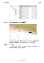
As of transceiver 21-216 revision 2, a rotary switch is added to the front panel to ease
installation and testing (see Figure
).
When two transceivers 21-216 are used in a PDH system, they are set as slaves when an
external clock is used.
Clock synchronization configuration
The rotary switch on the front panel has 16 positions (HEX switch). At position 0 the switch’s
arrow, visible through the adjusting hole, points straight down (see Figure
). In this position,
external clock is selected (default).
IEC07000249-1-en.vsdx
IEC07000249 V1 EN-US
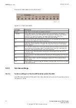
Figure 72: Rotary switch for clock synchronization configuration
Position
Function
0
External clock is selected (slave)
1
External clock is selected and inverted (slave)
2
Internal clock is selected (master)
3
Internal clock is selected and inverted (master)
4–7
Reserved for future use
8–15
Reserved for factory testing
Back-to-back testing
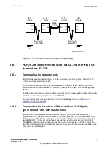
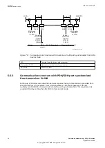
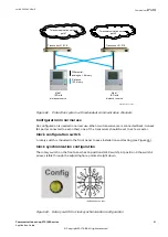
When performing back-to-back testing with G.703 ports directly connected, one transceiver
21-216 is set as a master (internal clock).
5.5.4
Power-up and LED statuses with transceiver 21–216
GUID-13DA5C8C-39C3-4643-87BF-31B9428DF496 v1
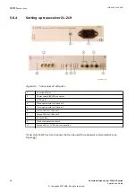
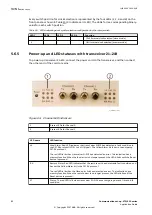
To power up transceiver 21–216, connect the power cord to the transceiver, and then connect
the other end of the cord to mains. If the link does not work, try to cross-connect the fibre at
one end.
1MRK 505 382-UEN E
Section 5
Communication set-up
Communication set-up, 670/650 series
73
Application Guide
© Copyright 2017 ABB. All rights reserved
Summary of Contents for Relion 670 series
Page 1: ...Relion 670 650 SERIES Communication set up 670 650 series Version 2 2 Application Guide...
Page 2: ......
Page 10: ...4...
Page 99: ...93...


