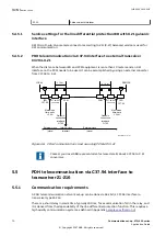
A maximum of 10 meter of cable is allowed to ensure the quality of the data (deviation from
X.21 standard cable length).
Synchronization
The X.21 LDCM works like a DTE (Data Terminal Equipment) and is normally expecting
synchronization from the DCE (Data Circuit Equipment). The transmission is normally
synchronized to the Signal Element Timing signal when a device is a DTE. When the signal is
high it will read the data at the receiver and when the signal is low it will write data to the
transmitter. This behaviour can be inverted in the control register.
Normally an external multiplexer is used and it should act like the master.
When two X.21 LDCM is directly communicating with each other one must be set as a master
generating the synchronization for the other (the slave). The DTE Signal Element Timing is
created from the internal 64 kHz clock.
The Byte Timing signal is not used in ABB devices.
5.4.4
Technical data
GUID-83EC40D0-ABCF-4292-B3DF-155C3A556B76 v4
Table 25: Galvanic X.21 line data communication module (X.21-LDCM)
Quantity
Range or value
Connector, X.21
Micro D-sub, 15-pole male, 1.27 mm (0.050") pitch
Connector, ground selection
2 pole screw terminal
Standard
CCITT X21
Communication speed
64 kbit/s
Insulation
1 kV
Maximum cable length
10 m
5.4.5
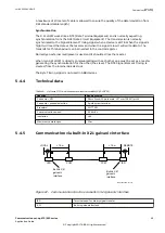
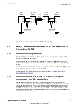
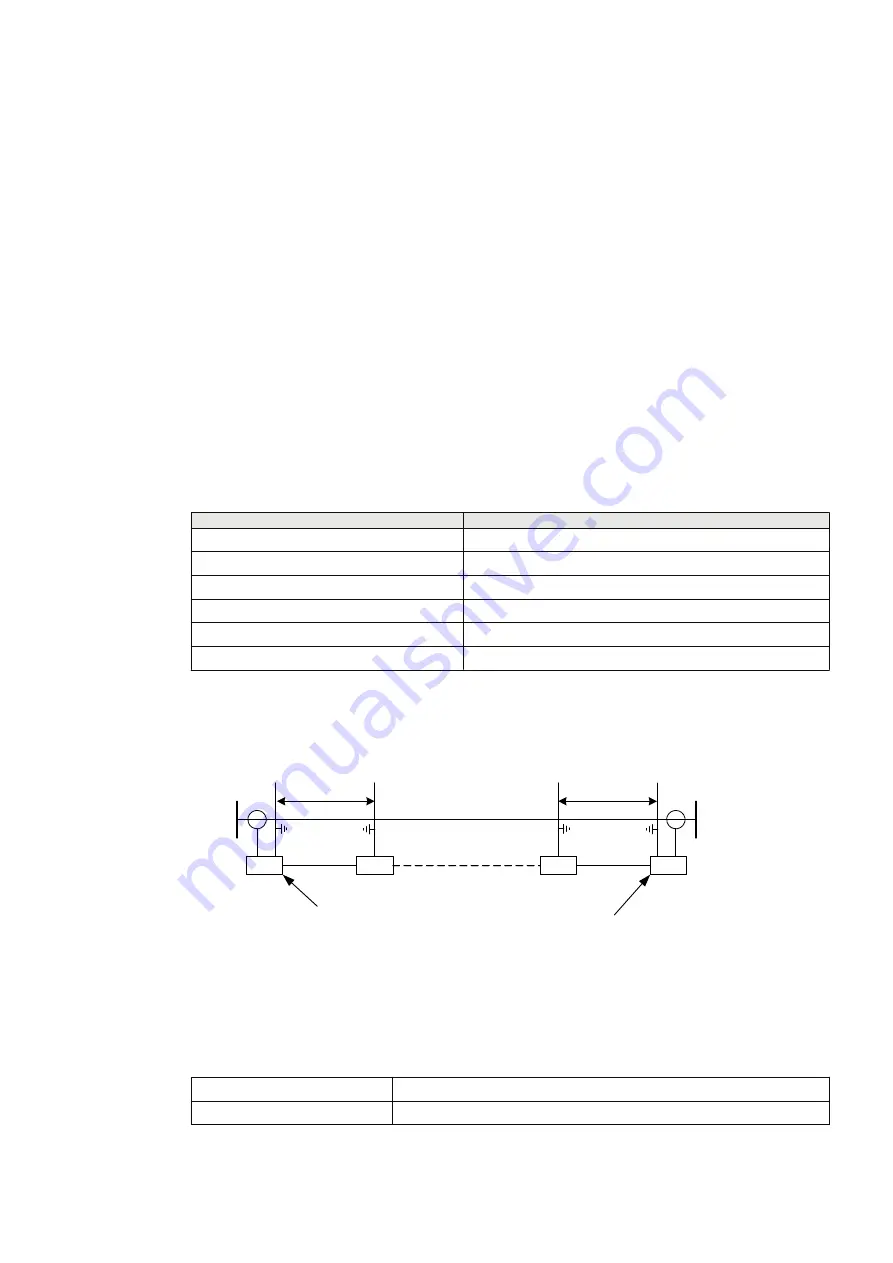
Communication via built-in X.21 galvanic interface
GUID-C0B90D43-0B15-4B17-835D-64114CF968E9 v1
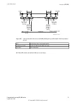
LOCAL
REMOTE
< 10 m
IED
PCM
IED
Built-in X.21
galvanic
interface
Built-in X.21
galvanic
interface
IEC07000259-2-en.vsdx
< 10 m
PCM
IEC07000259 V2 EN-US
Figure 67: Communication structure via built-in X.21 galvanic interface
IED
Terminal used for binary signal transfer
X.21
Built-in galvanic iterface
1MRK 505 382-UEN E
Section 5
Communication set-up
Communication set-up, 670/650 series
69
Application Guide
© Copyright 2017 ABB. All rights reserved
Summary of Contents for Relion 670 series
Page 1: ...Relion 670 650 SERIES Communication set up 670 650 series Version 2 2 Application Guide...
Page 2: ......
Page 10: ...4...
Page 99: ...93...


