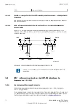
. If the telecommunication network is disturbed for more than
100 ms, an alarm will be issued.
5.5.2
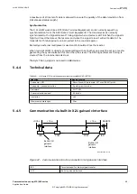
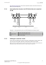
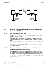
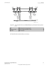
Communication structure via C37.94 interface to transceiver
21-216
GUID-0072DAE4-B2D8-4866-B820-4E7B3F8B1CDA v1
LOCAL
REMOTE
< 10 m
IED
C37.94
Transceiver
21-216xx
PCM
Multi-mode
fibre-optic
< 3 km
Galvanic
connection
interface
G.703
Internal clock
(master)
External clock
(slave)
External clock
IEC07000260-1-en.vsdx
IED
C37.94
< 10 m
Transceiver
21-216xx
PCM
(slave)
Galvanic
connection
interface
G.703
Multi-mode
fibre-optic
< 3 km
IEC07000260 V1 EN-US
Figure 69: Communication structure via C37.94 interface to transceiver 21–216
IED
Terminal used for binary signal transfer
Transceiver 21–216
Optical-to-electrical interface converter
PCM
Pulse code multiplexer
5.5.3
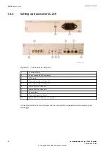
Setting up transceiver 21–216
GUID-0206E4D5-50DA-49E2-80E3-4F89A2540A7B v1
Confirm that the attenuation of the fibre-optic cable, including splices and patch cables, does
not exceed the system budget. Remember to add a safety margin (minimum 3dB).
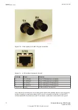
Make sure that the local fibre-optic transmitter (marked Tx) is connected to the remote unit's
fiber-optic receiver (marked Rx). Local Rx is to be connected to remote Tx.
1MRK 505 382-UEN E
Section 5
Communication set-up
Communication set-up, 670/650 series
71
Application Guide
© Copyright 2017 ABB. All rights reserved
Summary of Contents for Relion 670 series
Page 1: ...Relion 670 650 SERIES Communication set up 670 650 series Version 2 2 Application Guide...
Page 2: ......
Page 10: ...4...
Page 99: ...93...

