17.9.3
Design
17.9.3.1
General
The output signals can be of the types Disabled, Steady, or Pulse. The setting is done
on the MODE settings, common for the whole block, from PCM600.
•
0 = Disabled sets all outputs to 0, independent of the values sent from the station
level, that is, the operator station or remote-control gateway.
•
1 = Steady sets the outputs to a steady signal 0 or 1, depending on the values sent
from the station level.
•
2 = Pulse gives a pulse with one execution cycle duration, if a value sent from the
station level is changed from 0 to 1. That means that the configured logic
connected to the command function blocks may not have a cycle time longer than
the execution cycle time for the command function block.
17.9.4
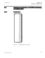
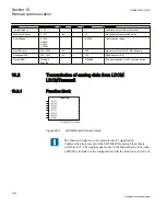
Function block
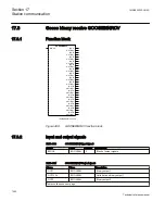
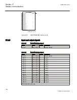
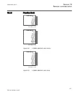
IEC06000007-2-en.vsd
MULTICMDRCV
BLOCK
ERROR
NEWDATA
OUTPUT1
OUTPUT2
OUTPUT3
OUTPUT4
OUTPUT5
OUTPUT6
OUTPUT7
OUTPUT8
OUTPUT9
OUTPUT10
OUTPUT11
OUTPUT12
OUTPUT13
OUTPUT14
OUTPUT15
OUTPUT16
VALID
IEC06000007 V2 EN
Figure 499:
MULTICMDRCV function block
1MRK505222-UUS C
Section 17
Station communication
1065
Technical reference manual
Summary of Contents for Relion 670 series
Page 1: ...Relion 670 series Line differential protection RED670 ANSI Technical reference manual...
Page 2: ......
Page 40: ...34...
Page 50: ...44...
Page 60: ...54...
Page 126: ...120...
Page 384: ...378...
Page 496: ...490...
Page 556: ...550...
Page 602: ...596...
Page 620: ...614...
Page 794: ...788...
Page 864: ...858...
Page 988: ...982...
Page 998: ...992...
Page 1084: ...1078...
Page 1164: ...1158...
Page 1168: ...1162...
Page 1220: ...1214...
Page 1230: ...1224...
Page 1231: ...1225...

