7.4.2.4
Base quantities within the protection
The base quantities shall be entered as setting parameters for everyground-fault
function. Base current (
IBase
) shall be entered as rated phase current of the protected
object in primary amperes. Base voltage (
VBase
) shall be entered as rated phase-to-
phase voltage of the protected object in primary kV.
7.4.2.5
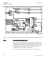
Internal ground-fault protection structure
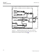
The protection is internally divided into the following parts:
1. Four residual overcurrent steps.
2. Directional supervision element for residual overcurrent steps with integrated
directional comparison step for communication based ground-fault protection
schemes (permissive or blocking).
3. Second harmonic blocking element with additional feature for sealed-in blocking
during switching of parallel transformers.
4. Switch on to fault feature with integrated Under-Time logic for detection of
breaker problems during breaker opening or closing sequence.
Each part is described separately in the following sections.
7.4.2.6
Four residual overcurrent steps
Each overcurrent step uses operating quantity Iop (residual current) as measuring
quantity. Each of the four residual overcurrent steps has the following built-in facilities:
•
Directional mode can be set to
Disabled
/
Non-directional
/
Forward
/
Reverse
. By
this parameter setting the directional mode of the step is selected. It shall be noted
that the directional decision (Forward/Reverse) is not made within the residual
overcurrent step itself. The direction of the fault is determined in common
“directional supervision element”.
•
Residual current pickup value.
•
Type of operating characteristic (inverse or definite time). By this parameter
setting it is possible to select inverse or definite time delay for the ground-fault
protection. Most of the standard IEC and ANSI inverse characteristics are
available. For the complete list of available inverse curves please refer to section
.
•
Type of reset characteristic (
Instantaneous
/
IEC Reset
/
ANSI Reset
). By this
parameter setting it is possible to select the reset characteristic of the step. For the
complete list of available reset curves please refer to section
Section 7
1MRK505222-UUS C
Current protection
404
Technical reference manual
Summary of Contents for Relion 670 series
Page 1: ...Relion 670 series Line differential protection RED670 ANSI Technical reference manual...
Page 2: ......
Page 40: ...34...
Page 50: ...44...
Page 60: ...54...
Page 126: ...120...
Page 384: ...378...
Page 496: ...490...
Page 556: ...550...
Page 602: ...596...
Page 620: ...614...
Page 794: ...788...
Page 864: ...858...
Page 988: ...982...
Page 998: ...992...
Page 1084: ...1078...
Page 1164: ...1158...
Page 1168: ...1162...
Page 1220: ...1214...
Page 1230: ...1224...
Page 1231: ...1225...

