7.11.2
Principle of operation
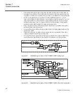
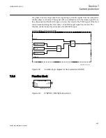
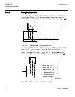
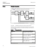
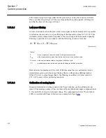
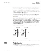
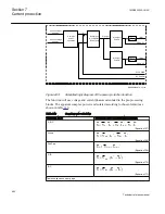
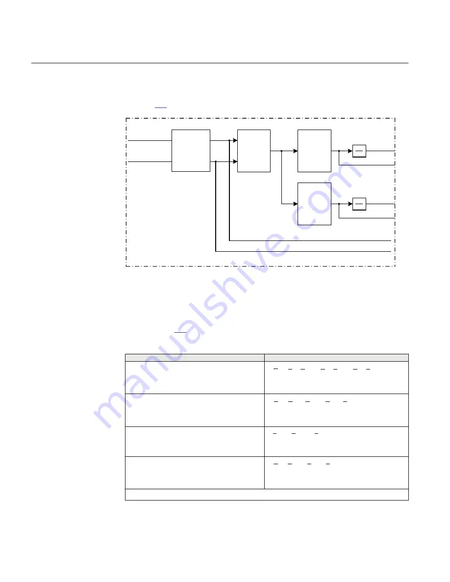
A simplified scheme showing the principle of the power protection function is shown
in figure
. The function has two stages with individual settings.
Chosen current
phasors
Chosen voltage
phasors
Complex
power
calculation
P
Derivation of
S( composant)
in Char angle
S( angle)
S( angle) <
Power1
t
TRIP 1
PICKUP1
Q
P = POWRE
Q = POWIM
S( angle) <
Power2
TRIP2
PICKUP2
0
t
0
ANSI06000438-2-en.vsd
ANSI06000438 V2 EN
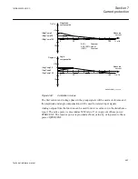
Figure 239:
Simplified logic diagram of the power protection function
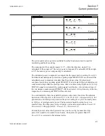
The function will use voltage and current phasors calculated in the pre-processing
blocks. The apparent complex power is calculated according to chosen formula as
shown in table
.
Table 233:
Complex power calculation
Set value:
Mode
Formula used for complex power calculation
A, B, C
*
*
*
A
A
B
B
C
C
S V
I
V
I
V
I
=
×
+
×
+
×
EQUATION2055-ANSI V1 EN
(Equation 97)
Arone
*
*
AB
A
BC
C
S V
I
V
I
=
×
-
×
EQUATION2056-ANSI V1 EN
(Equation 98)
PosSeq
*
3
PosSeq
PosSeq
S
V
I
= ×
×
EQUATION2057-ANSI V1 EN
(Equation 99)
AB
*
*
(
)
AB
A
B
S V
I
I
=
×
-
EQUATION2058-ANSI V1 EN
(Equation 100)
Table continues on next page
Section 7
1MRK505222-UUS C
Current protection
472
Technical reference manual
Summary of Contents for Relion 670 series
Page 1: ...Relion 670 series Line differential protection RED670 ANSI Technical reference manual...
Page 2: ......
Page 40: ...34...
Page 50: ...44...
Page 60: ...54...
Page 126: ...120...
Page 384: ...378...
Page 496: ...490...
Page 556: ...550...
Page 602: ...596...
Page 620: ...614...
Page 794: ...788...
Page 864: ...858...
Page 988: ...982...
Page 998: ...992...
Page 1084: ...1078...
Page 1164: ...1158...
Page 1168: ...1162...
Page 1220: ...1214...
Page 1230: ...1224...
Page 1231: ...1225...

