Table 2:
Function of selections
Selection
Function
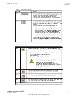
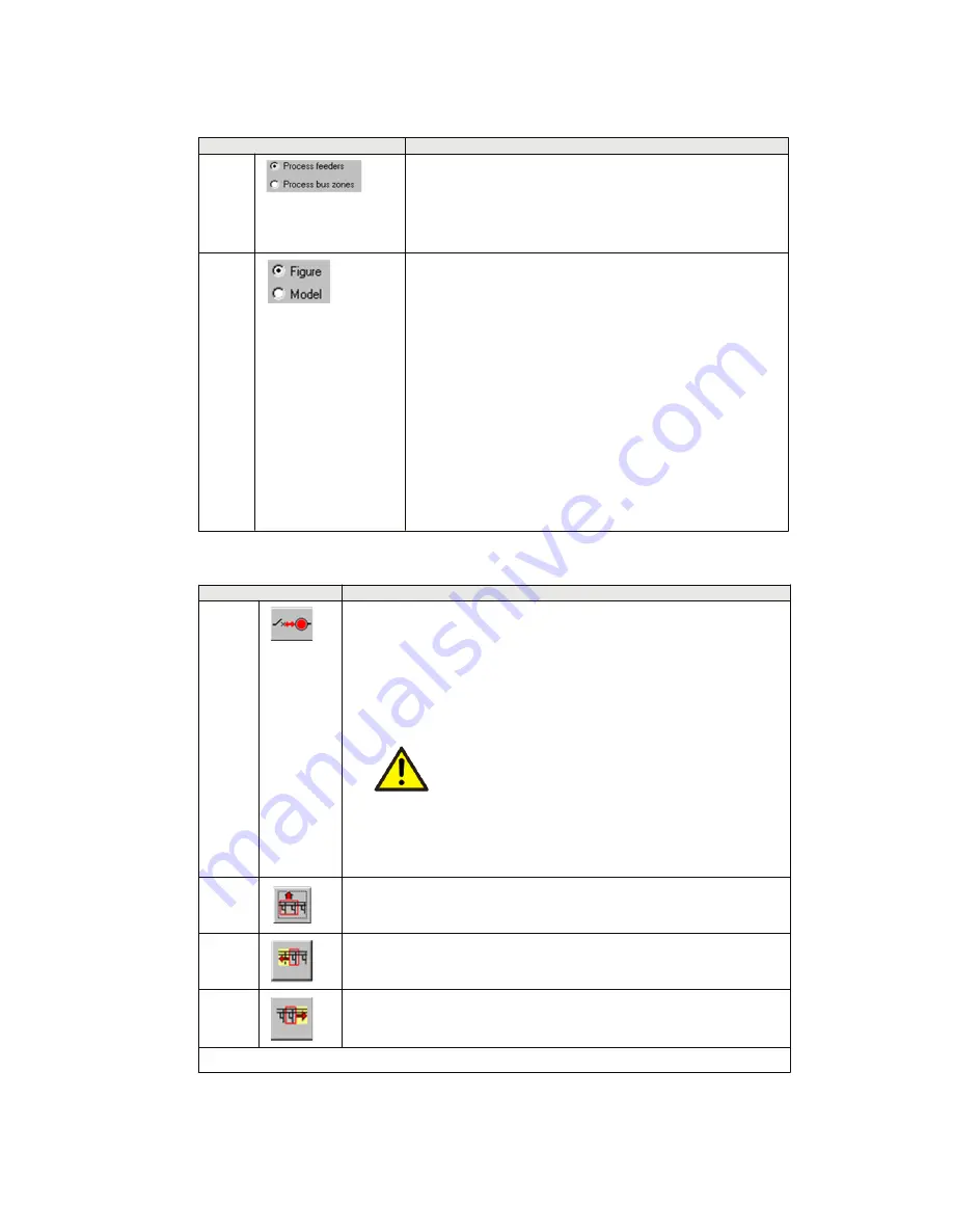
S1
The basic single-line editor mode is the ‘Process feeder’ mode.
Under this mode, the configuration of the single-line diagram
is defined. After the single-line (bus configuration) of the
complete station is finished, the (logical) bus zone
assignment has to be checked under the ‘Process bus zone’
mode.
S2
A Bay Model (BM) or a Bay Figure (BF) can be selected by a left
mouse click in the bay area. The selected BM or BF appears
marked with a red line rectangle (the BM is marked with a bold
rectangle)
The single-line editor provides two selection modes:
•
Figure: In this mode, a single Bay Figure (BF) can be
selected and moved to left, or the right side.
•
Model: In this mode, a complete Bay Model (BM) can be
selected and copied to the User model database, or
removed from the single-line diagram, or a BM can be
copied (imported) from the User model database, the
selected position in the single-line diagram.
For deleting BM(s) from the single-line diagram, or for the
import to the User model database, press SHIFT+left mouse
button on the BM. The view of the BM changes to bold framed
now.
Table 3:
Function of buttons
Button
Functions
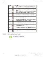
B1
The (physical) position of the CB and the CT in the single-line diagram
can be mutually exchanged (swapped). This button is only active, if a CT
object is selected.
1.
Select (exactly) the center of the CT object with a left mouse click.
The CT object appears filled with red color.
2.
Press button B1.
3.
The positions of CB and CT are exchanged now.
The single-line diagram including the CB/CT positions
configured with the HMI500 tool has to reflect the
substation’s bus configuration exactly.
There are bays where an exchange of the CB/CT
position is not possible (for example, coupler bays with
two CT’s). The swapping function for such bays is
blocked by the configurator tool.
B2
Copy a selected Bay Model under a new name into the User Model
Database. This button is active only, if the Model Mode (see S2) is
selected.
B3
Move the selected Bay Model or Bay Figure one position to the left. This
button is active only, if the Figure Mode (see S2) is selected.
B4
Move the selected Bay Model or Bay Figure one position to the right. This
button is active only, if the Figure Mode (see S2) is selected.
Table continues on next page
1MRK 511 452-UUS Rev. A
Section 5
Configuration
Distributed busbar protection REB500
21
Engineering manual
© 2020 Hitachi Power Grids. All rights reserved


