background image

1.  Application

M13637-3 v13

The Intelligent Electronic Device (IED) is used for the control,
protection and monitoring of different types of bays in power
networks. The IED is especially suitable for applications in
control systems where the IEC 61850–8–1 Ed 1 or Ed 2
station bus features of the IED can be fully utilized. It is used
for station-wide interlocking via GOOSE messages and
vertical client-server MMS communication to a local station or
remote SCADA operator workplace. This supports the
architecture with distributed control IEDs in all bays with high
demands on reliability. Redundant communication is obtained
through the built-in PRP and HSR features which can be used
in star or ringbus architectures. The IED can be used on all
voltage levels. It is suitable for the control of all apparatuses
in any type of switchgear arrangement.

The control is performed from remote (SCADA/Station)
through the IEC 61850–8–1 Ed1 or Ed2 station
communication or from the built-in multi-display local HMI.
Cyber security measures are implemented to secure safe
autonomous operation of the protection and control functions
even if simultaneous cyber attacks occur. For all common
types of switchgear arrangements, there are different pre-
configurations for control and interlocking. One control IED
can be used for single bay or multi-bay applications. The
control operation is based on the select-before-execute
principle to give highest possible security. There are
synchrocheck functions available to assist optimal breaker
closing at the right instance in synchronous as well as
asynchronous networks.

A number of protection functions are available for flexibility in
use for different station types and busbar arrangements. To
fulfil the user's application requirements, the IED features, for
example, up to six instantaneous phase and earth overcurrent
functions, 4–step directional or non-directional delayed-phase
and earth overcurrent functions, thermal overload and
frequency functions, two instances of 2–step under- and
overvoltage functions, autorecloser functions and several
different measuring functions. This, together with the multi-
display local HMI that can show one or more pages per
feeder allows using the IED for protection and control for up
to six bays in a substation.

The auto-reclose for single-, two-, and/or three-phase reclose
includes priority circuits for multi-breaker arrangements. It co-
operates with the synchrocheck function with high-speed or
delayed reclosing. Several breaker failure functions are
available to provide a breaker failure function independent
from the protection IEDs, also for a complete one- and a half
breaker diameter.

Disturbance recording and fault locator are available to allow
independent post-fault analysis after primary disturbances in
case of a failure in the protection system.

Duplex communication channels for transfer of up to 192
intertrip and binary signals are available on each remote-end
data communication card (LDCM). Typical applications are
the communication between IEDs inside the station or with
IEDs in a remote station as remote I/O.

The IED can be used in applications with the IEC/UCA
61850-9-2LE process bus with up to eight Merging Units
(MU). Each MU has eight analogue channels, four current and
four voltages. Conventional input transformer module and
Merging Unit channels can be mixed freely in your application.

Logic is prepared with a graphical tool. The advanced logic
capability allows special applications such as automatic
opening of disconnectors in multi-breaker arrangements,
closing of breaker rings, load transfer logics and so on. The
graphical configuration tool ensures simple and fast testing
and commissioning.

Forcing of binary inputs and outputs is a convenient way to
test wiring in substations as well as testing configuration logic
in the IEDs. Basically it means that all binary inputs and
outputs on the IED I/O modules (BOM, BIM, IOM & SOM) can
be forced to arbitrary values.

Central Account Management is an authentication
infrastructure that offers a secure solution for enforcing
access control to IEDs and other systems within a substation.
This incorporates management of user accounts, roles and
certificates and the distribution of such, a procedure
completely transparent to the user.

Flexible Product Naming allows the customer to use an IED-
vendor independent IEC 61850 model of the IED. This
customer model will be used as the IEC 61850 data model,
but all other aspects of the IED will remain unchanged (e.g.,
names on the local HMI and names in the tools). This offers
significant flexibility to adapt the IED to the customers'
system and standard solution.

SEMOD51278-4 v11

Four packages have been defined for following applications:

• Single breaker (double or single bus) arrangement (A30)
• Double breaker arrangement (B30)
• 1 ½ breaker arrangement for a complete diameter (C30)
• Single breaker (double bus) arrangement with PMU

functionality (D30)

Optional functions are available in PCM600 Application
Configuration Tool and can be configured by the user.
Interface to analog and binary IO:s are configurable without
need of configuration changes. Analog and control circuits
have been pre-defined. Other signals need to be applied as
required for each application. The main differences between
the packages above are the interlocking modules and the
number of apparatuses to control.

1MRK 511 404-BEN A

Bay control REC670 2.2


Product version: 2.2.1

Issued: October 2017

Revision: A

ABB

3

Summary of Contents for Relion REC670

Page 1: ...RELION 670 SERIES Bay control REC670 Version 2 2 Product guide...

Page 2: ...2 22 Connection diagrams 45 23 Technical data 46 24 Ordering for customized IED 116 25 Ordering for pre configured IED 127 26 Ordering for Accessories 133 Disclaimer The information in this document i...

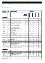
Page 3: ...e and a half breaker diameter Disturbance recording and fault locator are available to allow independent post fault analysis after primary disturbances in case of a failure in the protection system Du...

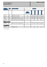
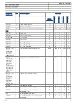
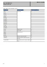
Page 4: ...IN LF PTTR 26 SDE PSDE 67N IN UV2 PTUV 27 2 3U SA PTOF 81 f OV2 PTOV 59 2 3U GOP PDOP 32 P SA PFRC 81 df dt GUP PDUP 37 P TR PTTR 49 CV GAPC 2 I U LMB RFLO 21FL FL EC PSCH 85 TR8 ATCC 90 U ECRW PSCH...

Page 5: ...PTTR 26 C MMXU MET I C MSQI MET Isqi FUF SPVC U I WA1 WA2_VT WA1_VT WA2 LINE_VT LINE_CT1 LINE_CT2 S CILO 3 Control S CSWI 3 Control S XSWI 3 Control S CILO 3 Control S CSWI 3 Control S XSWI 3 Control...

Page 6: ...F4 PTOC 51N_67N 4 IN GOP PDOP 32 P GUP PDUP 37 P LMB RFLO 21FL FL EC PSCH 85 ECRW PSCH 85 SMP PTRC 94 1 0 Q CRSV 3 Control C MMXU MET I C MSQI MET Isqi C MMXU MET I C MSQI MET Isqi WA1 WA2_VT FUF SPVC...

Page 7: ...GOP PDOP 32 P GUP PDUP 37 P CV GAPC 2 I U LMB RFLO 21FL FL EC PSCH 85 ECRW PSCH 85 VD SPVC 60 Ud SMP PTRC 94 1 0 CC RBRF 50BF 3I BF VN MMXU MET UN V MMXU MET U V MSQI MET Usqi C MMXU MET I C MSQI MET...

Page 8: ...ns included in the product by default All parameters should be verified by the customer since these are specific to the system object or application Optional functions and optional IO ordered will not...

Page 9: ...AAC B386 B38B57718BD2 v13 Table 1 Example of quantities 2 number of basic instances 0 3 option quantities 3 A03 optional function included in packages A03 refer to ordering details IEC 61850 or functi...

Page 10: ...26 Thermal overload protection one time constant Fahrenheit 0 6 1 C51 1 C52 2 C53 1 C51 TRPTTR 49 Thermal overload protection two time constants 0 6 1 C51 1 C52 2 C53 1 C51 CCRBRF 50BF Breaker failure...

Page 11: ...6 6 E01 6 E01 6 E01 6 E01 SAPFRC 81 Rate of change of frequency protection 0 6 6 E01 6 E01 6 E01 6 E01 FTAQFVR 81A Frequency time accumulation protection 0 12 Multipurpose protection CVGAPC General c...

Page 12: ...90 Automatic voltage control for tap changer parallel control 0 4 1 H15 1 H15 2 H18 1 H15 TCMYLTC 84 Tap changer control and supervision 6 binary inputs 0 4 4 4 4 4 TCLYLTC 84 Tap changer control and...

Page 13: ...D GATE INV LLD OR PULSETIMER RSMEMORY SRMEMORY TIMERSET XOR Basic configurable logic blocks see Table 2 40 420 40 420 40 420 40 420 40 420 ANDQT INDCOMBSPQT INDEXTSPQT INVALIDQT INVERTERQT ORQT PULSET...

Page 14: ...2 12 12 12 12 INTCOMP Comparator for integer inputs 30 30 30 30 30 REALCOMP Comparator for real inputs 30 30 30 30 30 Table 2 Total number of instances for basic configurable logic blocks Basic config...

Page 15: ...1 DB_BUS_A 1 DB_BUS_B 1 DB_LINE 1 ABC_LINE 1 AB_TRAFO 1 SCSWI Switch controller 10 SXSWI Circuit switch 9 QCRSV Apparatus control 2 RESIN1 1 RESIN2 59 POS_EVAL Evaluation of position indication 10 XL...

Page 16: ...1 DB_BUS_A 1 DB_BUS_B 1 DB_LINE 1 ABC_LINE 1 AB_TRAFO 1 SCSWI Switch controller 15 SXSWI Circuit switch 14 QCRSV Apparatus control 2 RESIN1 1 RESIN2 59 POS_EVAL Evaluation of position indication 15 X...

Page 17: ...aluation of position indication 30 QCBAY Bay control 5 LOCREM Handling of LR switch positions 5 XLNPROXY Proxy for signals from switching device via GOOSE 42 GOOSEXLNRCV GOOSE function block to receiv...

Page 18: ...ckage Extended configurable logic block Total number of instances AND 180 GATE 49 INV 180 LLD 49 OR 180 PULSETIMER 89 RSMEMORY 40 SLGAPC 74 SRMEMORY 130 TIMERSET 109 VSGAPC 120 XOR 89 1MRK 511 404 BEN...

Page 19: ...3 3 3 RANGE_XP Measured value expander block 66 66 66 66 66 SSIMG 63 Insulation supervision for gas medium 21 21 21 21 21 SSIML 71 Insulation supervision for liquid medium 3 3 3 3 3 SSCBR Circuit brea...

Page 20: ...ntrol REC670 Customized REC670 A30 REC670 B30 REC670 C30 REC670 D30 Metering PCFCNT Pulse counter logic 16 16 16 16 16 ETPMMTR Function for energy calculation and demand handling 6 6 6 6 6 1MRK 511 40...

Page 21: ...ion protocol 1 1 1 1 1 DNPFREC DNP3 0 fault records for TCP IP and EIA 485 communication protocol 1 1 1 1 1 IEC 61850 8 1 IEC 61850 1 1 1 1 1 GOOSEINTLKRCV Horizontal communication via GOOSE for inter...

Page 22: ...gging 1 1 1 1 1 ALTRK Service tracking 1 1 1 1 1 PRP IEC 62439 3 Parallel redundancy protocol 0 1 1 P23 1 P23 1 P23 1 P23 HSR IEC 62439 3 High availability seamless redundancy 0 1 1 P24 1 P24 1 P24 1...

Page 23: ...nd weak end infeed logic for distance protection 0 1 1 K01 1 K01 1 K01 1 K01 ZCLCPSCH Local acceleration logic 0 1 1 K01 1 K01 1 K01 1 K01 ECPSCH 85 Scheme communication logic for residual overcurrent...

Page 24: ...TGRPS Number of setting groups ACTVGRP Parameter setting groups TESTMODE Test mode functionality CHNGLCK Change lock function SMBI Signal matrix for binary inputs SMBO Signal matrix for binary outputs...

Page 25: ...eature evaluates voltage difference phase angle difference slip frequency and frequency rate of change before issuing a controlled closing of the circuit breaker Breaker closing time is a setting Auto...

Page 26: ...to each IED and is not dependent on any central function For the station wide interlocking the IEDs communicate via the system wide interbay bus IEC 61850 8 1 or by using hard wired binary inputs out...

Page 27: ...lel transformers and this is provided for within IEC 61850 8 1 Voltage control includes many extra features such as the possibility to avoid simultaneous tapping of parallel transformers hot stand by...

Page 28: ...protocols Protocol reporting via IEEE 1344 and C37 118 PMUREPORT GUID 8DF29209 252A 4E51 9F4A B14B669E71AB v4 The phasor measurement reporting block moves the phasor calculations into an IEEE C37 118...

Page 29: ...NS4PTOC can also be used to provide a system backup for example in the case of the primary protection being out of service due to communication or voltage transformer circuit failure Directional oper...

Page 30: ...ormally the own breaker is tripped to correct such a situation If the situation persists the surrounding breakers should be tripped to clear the unsymmetrical load situation The Pole discordance prote...

Page 31: ...ency protection SAPTUF M13349 3 v13 Underfrequency occurs as a result of a lack of generation in the network Underfrequency protection SAPTUF measures frequency with high accuracy and is used for load...

Page 32: ...t functions Current circuit supervision CCSSPVC compares the residual current from a three phase set of current transformer cores with the neutral point current on a separate input taken from another...

Page 33: ...be transmitted to the other line end With directional comparison a short operate time of the protection including a channel transmission time can be achieved This short operate time enables rapid auto...

Page 34: ...our inputs and two outputs One of the outputs is inverted GATE function block is used for whether or not a signal should be able to pass from the input to the output INVERTER function block that inver...

Page 35: ...ble logic blocks Fixed signal function block FXDSIGN M15322 3 v12 The Fixed signals function FXDSIGN has nine pre set fixed signals that can be used in the configuration of an IED either for forcing t...

Page 36: ...me to the end of post fault time will be included in the recording Disturbance record will have visible settings from all function instances that are configured in the application configuration tool E...

Page 37: ...cation function for measured values MVGAPC SEMOD55872 5 v10 Generic communication function for measured values MVGAPC function is used to send the instantaneous value of an analog signal to other syst...

Page 38: ...ure at a given time This value can either be a measured value taken through sensors or the one calculated by the function This decision is made based on the top oil temperature sensor quality Top oil...

Page 39: ...he synchronization of the IED when it is a part of a control and a protection system This makes it possible to compare events and disturbance data between all IEDs within a station automation system a...

Page 40: ...M bus Available communication protocols are IEC 61850 8 1 communication protocol IEC UCA 61850 9 2LE communication protocol LON communication protocol SPA communication protocol IEC 60870 5 103 commun...

Page 41: ...user defined input signals in monitor direction These function blocks include the FunctionType parameter for each block in the private range and the information number parameter for each input signal...

Page 42: ...tical to galvanic conversion for connection to a multiplexer These units are designed for 64 kbit s resp 2Mbit s operation The converter is delivered with 19 rack mounting accessories 21 Hardware desc...

Page 43: ...rest are slaves No special control signal is needed in this case GPS time synchronization module GTM M14851 3 v4 This module includes a GPS receiver used for time synchronization The GPS has one SMA...

Page 44: ...9 10 47 448 3 17 65 242 1 9 53 255 8 10 07 430 3 16 86 190 5 7 50 428 3 16 86 465 1 18 31 228 6 9 00 482 6 19 00 The H and K dimensions are defined by the 19 rack mounting kit Mounting alternatives M...

Page 45: ...s for IEC Customized products Connection diagram 670 series 2 2 1MRK002801 AG Connection diagrams for Configured products Connection diagram REC670 2 2 A30X00 1MRK002807 CA Connection diagram REC670 2...

Page 46: ...t in accordance with the associated main instrument transformers Note that for functions which measure an analogue signal which do not have corresponding primary quantity the 1 1 ratio shall be set fo...

Page 47: ...r 1 s 30 Ir for 10 s 10 Ir for 1 min 4 Ir continuously Dynamic withstand 250 Ir one half wave Burden 20 mVA at Ir 1 A 150 mVA at Ir 5 A max 350 A for 1 s when COMBITEST test switch is included Voltage...

Page 48: ...VA at 220 V all values for individual voltage inputs Note All current and voltage data are specified as RMS values at rated frequency M6389 1 v5 Table 13 MIM mA input module Quantity Rated value Nomin...

Page 49: ...EL 100 250 V EL 20 EL 20 Power consumption 50 W typically Auxiliary DC power in rush 10 A during 0 1 s Binary inputs and outputs IP15844 1 v1 M12576 1 v9 Table 17 BIM Binary input module Quantity Rate...

Page 50: ...ing settable 1 40 Hz Release settable 1 30 Hz Debounce filter Settable 1 20 ms Maximum 176 binary input channels may be activated simultaneously with influencing factors within nominal range M12573 1...

Page 51: ...resistive load 0 2 s 1 0 s 30 A 10 A 220 250 V 0 4 A 110 125 V 0 4 A 48 60 V 0 2 A 24 30 V 0 1 A Breaking capacity for AC cos 0 4 250 V 8 0 A 250 V 8 0 A Breaking capacity for DC with L R 40 ms 48 V...

Page 52: ...sistive load 0 2 s 1 0 s 30 A 10 A 220 250 V 0 4 A 110 125 V 0 4 A 48 60 V 0 2 A 24 30 V 0 1 A Breaking capacity for AC cos j 0 4 250 V 8 0 A 250 V 8 0 A Breaking capacity for DC with L R 40 ms 48 V 1...

Page 53: ...nce open state 300 k 810 k Test voltage across open contact 1 min No galvanic separation No galvanic separation Current carrying capacity Continuous 5 A 5 A 1 0 s 10 A 10 A Making capacity at capaciti...

Page 54: ...Trip and Signal relays Binary outputs 24 Max system voltage 250 V AC DC Test voltage across open contact 1 min 1000 V rms Current carrying capacity Per relay continuous Per relay 1 s Per process conne...

Page 55: ...Restart time 300 s Table 27 Frequency influence reference standard IEC 60255 1 Dependence on Within nominal range Influence Frequency dependence operate value fr 2 5 Hz for 50 Hz fr 3 0 Hz for 60 Hz...

Page 56: ...test 150 300 V 50 Hz IEC 60255 26 Zone A Conducted common mode immunity test 15 Hz 150 kHz IEC 61000 4 16 Class IV Power frequency magnetic field test 1000 A m 3 s 100 A m cont IEC 61000 4 8 Class V P...

Page 57: ...humidity 93 IEC 60068 2 78 Damp heat test cyclic Test Db for 6 cycles at 25 to 55 C and humidity 93 to 95 1 cycle 24 hours IEC 60068 2 30 Table 31 CE compliance Test According to Immunity EN 60255 26...

Page 58: ...900 V Maximum continuous power U Trip2 SeriesResistor 200 W Operate time at 0 to 10 x Ud Min 5 ms Max 15 ms Reset time at 10 x Ud to 0 Min 75 ms Max 95 ms Critical impulse time 2 ms typically at 0 to...

Page 59: ...ty Range Accuracy Signal frequency 0 1 x fr 1 0 TVE Signal magnitude Voltage phasor Current phasor 0 1 1 2 x Ur 0 5 2 0 x Ir Phase angle 180 Harmonic distortion 10 from 2nd 50th Interfering signal Mag...

Page 60: ...f IBase Operate time at 0 to 2 x Iset Min 15 ms Max 25 ms Reset time at 2 x Iset to 0 Min 15 ms Max 25 ms Critical impulse time 10 ms typically at 0 to 2 x Iset Operate time at 0 to 10 x Iset Min 5 ms...

Page 61: ...7 Operate time start non directional at 0 to 2 x Iset Min 15 ms Max 30 ms Reset time start non directional at 2 x Iset to 0 Min 15 ms Max 30 ms Operate time start non directional at 0 to 10 x Iset Min...

Page 62: ...5 Table 156 and Table 157 16 curve types See Table 155 Table 156 and Table 157 Second harmonic blocking 5 100 of fundamental 2 0 of Ir Minimum polarizing voltage 1 100 of UBase 0 5 of Ur Minimum polar...

Page 63: ...teristic angle RCA 180 to 180 degrees 2 0 degrees Operate current for directional release 1 100 of IBase For RCA 60 degrees 2 5 of Ir at I Ir 2 5 of I at I Ir Minimum polarizing voltage 1 100 of UBase...

Page 64: ...0 5 of U at U Ur Operate time for non directional residual overcurrent at 0 to 2 x Iset Min 40 ms Max 65 ms Reset time for non directional residual overcurrent at 2 x Iset to 0 Min 40 ms Max 65 ms Ope...

Page 65: ...F 2 0 C 4 0 F Operate temperature 0 300 C 0 600 F 2 0 C 4 0 F Reset level temperature 0 300 C 0 600 F 2 0 C 4 0 F M13266 2 v8 Table 42 Thermal overload protection two time constants TRPTTR Function R...

Page 66: ...reater Additional time delay for a second back up trip at 0 to 2 x Iset 0 000 60 000 s 0 2 or 20 ms whichever is greater Time delay for alarm for faulty circuit breaker 0 000 60 000 s 0 2 or 15 ms whi...

Page 67: ...degrees 2 0 degrees Operate time start at 0 5 x Sr to 2 x Sr and k 0 000 Min 10 ms Max 25 ms Reset time start at 2 x Sr to 0 5 x Sr and k 0 000 Min 35 ms Max 55 ms Independent time delay to operate f...

Page 68: ...of S at S Sr Operate value voltage protection function for harmonic overload Definite time 10 500 0 5 of Ur at U Ur 0 5 of U at U Ur Operate value voltage protection function for harmonic overload Inv...

Page 69: ...e types See tables 155 and 156 Minimum operate time for inverse time characteristics 0 00 60 00 s 0 2 or 35 ms whichever is greater High voltage limit voltage dependent operation 30 0 100 0 of UBase 1...

Page 70: ...00 6000 00 s 0 2 or 40ms whichever is greater Definite time delay step 2 at 1 2 x Uset to 0 0 000 60 000 s 0 2 or 40ms whichever is greater Minimum operate time inverse characteristics 0 000 60 000 s...

Page 71: ...s whichever is greater Definite time delay high step step 2 at 0 to 1 2 x Uset 0 000 60 000 s 0 2 or 45 ms whichever is greater Minimum operate time Inverse characteristics 0 000 60 000 s 0 2 or 45 ms...

Page 72: ...15 ms Max 30 ms Operate time start at 0 to 1 2 x Uset Min 20 ms Max 35 ms Reset time start at 1 2 x Uset to 0 Min 5 ms Max 25 ms Critical impulse time 10 ms typically at 0 to 2 x Uset Impulse margin...

Page 73: ...chever is greater Time delay for enabling the functions after restoration 0 000 60 000 s 0 2 or 35 ms whichever is greater Operate time delay when disconnecting all three phases 0 000 60 000 s 0 2 or...

Page 74: ...f Ubase UMin 50 150 of Ubase Exponent 0 0 5 0 tMax 0 010 60 000 s tMin 0 010 60 000 s 1 0 or 100 ms whichever is greater Exponent U UMin t tMax tMin tMin UNom UMin EQUATION1182 V1 EN US Equation 3 U U...

Page 75: ...tion Range or value Accuracy Operate value frequency high limit level at symmetrical three phase voltage 35 00 90 00 Hz 2 0 mHz Operatevalue frequency low limit level at symmetrical three phase voltag...

Page 76: ...Multipurpose protection M13095 2 v8 1MRK 511 404 BEN A Bay control REC670 2 2 Product version 2 2 1 76 ABB...

Page 77: ...set to 0 step 1 2 0 00 6000 00 s 0 2 or 35 ms whichever is greater Overcurrent non directional Start time at 0 to 2 x Iset Min 15 ms Max 30 ms Reset time at 2 x Iset to 0 Min 15 ms Max 30 ms Start tim...

Page 78: ...ble 163 Undervoltage Inverse time characteristics see table 164 3 curve types See table 164 High and low voltage limit voltage dependent operation step 1 2 1 0 200 0 of UBase 1 0 of Ur at U Ur 1 0 of...

Page 79: ...ction CVGAPC continued Function Range or value Accuracy Undervoltage Critical impulse time 10 ms typically at 1 2 x Uset to 0 8 x Uset Impulse margin time 15 ms typically 1MRK 511 404 BEN A Bay contro...

Page 80: ...perate current zero sequence 1 100 of IBase 0 5 of Ir Operate voltage negative sequence 1 100 of UBase 0 5 of Ur Operate current negative sequence 1 100 of IBase 0 5 of Ir Operate voltage change level...

Page 81: ...fuse failure at 1 x Ur to 0 Min 5 ms Max 15 ms Reset time block of main fuse failure at 0 to 1 x Ur Min 15 ms Max 30 ms Operate value alarm for pilot fuse failure 10 0 80 0 of UBase 0 5 of Ur Reset r...

Page 82: ...tween bus and line for synchronizing 15 30 degrees 2 0 degrees Breaker closing pulse duration 0 050 1 000 s 0 2 or 15 ms whichever is greater tMaxSynch which resets synchronizing function if no close...

Page 83: ...or 15 ms whichever is greater Circuit breaker closing pulse duration tPulse 0 000 60 000 s 0 2 or 15 ms whichever is greater Reclaim time tReclaim 0 00 6000 00 s 0 2 or 15 ms whichever is greater Maxi...

Page 84: ...se Load voltage auto correction 20 0 20 0 of UBase Duration time for the reverse action block signal 30 6000 s 0 2 or 600 ms whichever is greater Current limit for reverse action block 0 100 of I1Base...

Page 85: ...tion change before the value is accepted 1 60 s 0 2 or 200 ms whichever is greater Tap changer constant time out 1 120 s 0 2 or 200 ms whichever is greater Raise lower command output pulse duration 0...

Page 86: ...is greater Operation mode of unblocking logic Off NoRestart Restart M16039 1 v16 Table 68 Current reversal and weak end infeed logic for distance protection ZCRWPSCH Function Range or value Accuracy...

Page 87: ...r value 0 000 60 000 s 0 2 or 35 ms whichever is greater M16051 2 v11 Table 71 Current reversal and weak end infeed logic for residual overcurrent protection ECRWPSCH Function Range or value Accuracy...

Page 88: ...B instances Function Quantity with cycle time 3 ms 8 ms 100 ms STARTCOMB 32 GUID 3AB1EE95 51BF 4CC4 99BD F4ECDAACB75A v1 Table 75 Number of TMAGAPC instances Function Quantity with cycle time 3 ms 8 m...

Page 89: ...ms 100 ms LLD 10 10 20 GUID 35A795D7 A6BD 4669 A023 43C497DBFB01 v3 Table 83 Number of OR instances Logic block Quantity with cycle time 3 ms 8 ms 100 ms OR 78 60 160 GUID E05E5FB1 23E7 4816 84F2 1FB...

Page 90: ...SPQT instances Logic block Quantity with cycle time 3 ms 8 ms 100 ms INDCOMBSPQT 10 10 GUID C1E61AE5 22CF 4198 97CF 8C8043EE96D2 v1 Table 91 Number of INDEXTSPQT instances Logic block Quantity with cy...

Page 91: ...41562FB 6149 495B 8A63 200DF16A5590 v1 Table 97 Number of SRMEMORYQT instances Logic block Quantity with cycle time 3 ms 8 ms 100 ms SRMEMORYQT 10 30 GUID B6231B97 05ED 40E8 B735 1E1A50FDB85F v1 Table...

Page 92: ...mber of B16I instances Function Quantity with cycle time 3 ms 8 ms 100 ms B16I 6 4 8 GUID 3820F464 D296 4CAD 8491 F3F997359D79 v1 Table 102 Number of BTIGAPC instances Function Quantity with cycle tim...

Page 93: ...9 9 s 0 2 or 250 ms whichever is greater Table 106 Number of TEIGAPC instances Function Quantity with cycle time 3 ms 8 ms 100 ms TEIGAPC 4 4 4 GUID CEA332FF 838D 42B7 AEFC C1E87809825E v2 Table 107 N...

Page 94: ...0 1 4 0 x Ir 0 5 of Sr at S 0 5 x Sr 0 5 of S at S 0 5 x Sr 100 to 220 V 0 5 2 0 x Ir 0 2 of S Power factor cos 10 to 300 V 0 1 4 0 x Ir 0 02 100 to 220 V 0 5 2 0 x Ir 0 01 GUID 5E04B3F9 E1B7 4974 9C...

Page 95: ...0 5 Ir 0 5 degrees at 0 5 Ir I 4 0 Ir GUID 47094054 A828 459B BE6A D7FA1B317DA7 v6 Table 114 Voltage sequence measurement VMSQI Function Range or value Accuracy Voltage positive sequence U1 10 to 300...

Page 96: ...rate 1 kHz at 50 Hz 1 2 kHz at 60 Hz Recording bandwidth 5 300 Hz GUID F034B396 6600 49EF B0A5 8ED96766A6A0 v7 Table 117 Insulation supervision for gas medium function SSIMG Function Range or value A...

Page 97: ...greater GUID B6799420 D726 460E B02F C7D4F1937432 v8 Table 119 Circuit breaker condition monitoring SSCBR Function Range or value Accuracy Alarm level for open and close travel time 0 200 ms 3 ms Alar...

Page 98: ...122 Event list Function Value Buffer capacity Maximum number of events in the list 1000 Resolution 1 ms Accuracy Depending on time synchronizing M13765 1 v5 Table 123 Indications Function Value Buffer...

Page 99: ...8328 754C238F4AD0 v3 Table 127 Event counter with limit supervision L4UFCNT Function Range or value Accuracy Counter value 0 65535 Max count up speed 30 pulses s 50 duty cycle GUID F5E124E3 0B85 41AC...

Page 100: ...le time for report of counter value 1 3600 s SEMOD153707 2 v5 Table 130 Function for energy calculation and demand handling ETPMMTR Function Range or value Accuracy Energy metering kWh Export Import k...

Page 101: ...00 38400 Bd GUID E8B5405C 241C 4DC2 8AB1 3FA77343A4DE v2 Table 132 IEC 61850 9 2 communication protocol Function Value Protocol IEC 61850 9 2 Communication speed for the IEDs 100BASE FX M11927 1 v2 Ta...

Page 102: ...iber diameter Glass fiber 62 5 125 mm Plastic fiber 1 mm depending on optical budget calculation SEMOD158710 2 v2 Table 138 Galvanic RS485 communication module Quantity Range or value Communication sp...

Page 103: ...m 50 mile 26 dB typical distance 110 km 68 mile Graded index multimode 50 125 mm 9 dB typical distance about 2 km 1 mile Optical connector Type ST Type FC PC Type FC PC Protocol C37 94 C37 94 implemen...

Page 104: ...otective earthed Overvoltage category III Pollution degree 2 normally only non conductive pollution occurs except that occasionally a temporary conductivity caused by condensation is to be expected Co...

Page 105: ...ommunication ports NUM 4 Ethernet ports 1 Basic 3 Optional Ethernet connection type SFP Optical LC or Galvanic RJ45 Carrier modules supported OEM LDCM GUID 4876834C CABB 400B B84B 215F65D8AF92 v2 Tabl...

Page 106: ...ock BC Ordinary Clock OC Transparent Clock TC Accuracy According to standard IEC IEEE 61850 9 3 Number of nodes According to standard IEC IEEE 61850 9 3 Ports supported All rear Ethernet ports SEMOD55...

Page 107: ...litude modulated low level high level 1 3 Vpp 3 x low level max 9 Vpp Supported formats IRIG B 00x IRIG B 12x Accuracy 10 s for IRIG B 00x and 100 s for IRIG B 12x Input impedance 100 k ohm Optical co...

Page 108: ...IEEE C37 112 2 0 or 40 ms whichever is greater ANSI Extremely Inverse A 28 2 B 0 1217 P 2 0 tr 29 1 ANSI Very inverse A 19 61 B 0 491 P 2 0 tr 21 6 ANSI Normal Inverse A 0 0086 B 0 0185 P 0 02 tr 0 4...

Page 109: ...PR TR t k I CR EQUATION1253 SMALL V1 EN US I Imeasured Iset k 0 05 999 in steps of 0 01 A 0 005 200 000 in steps of 0 001 B 0 00 20 00 in steps of 0 01 C 0 1 10 0 in steps of 0 1 P 0 005 3 000 in step...

Page 110: ...10 k 2 00 1 5 x Iset I 20 x Iset ANSI IEEE C37 112 5 0 or 160 ms whichever is greater ANSI Extremely Inverse A 28 2 B 0 1217 P 2 0 tr 29 1 ANSI Very inverse A 19 61 B 0 491 P 2 0 tr 21 6 ANSI Normal...

Page 111: ...PR TR t k I CR EQUATION1253 SMALL V1 EN US I Imeasured Iset k 0 05 999 in steps of 0 01 A 0 005 200 000 in steps of 0 001 B 0 00 20 00 in steps of 0 01 C 0 1 10 0 in steps of 0 1 P 0 005 3 000 in step...

Page 112: ...ely Inverse A 0 0515 B 0 1140 P 0 02 tr 4 85 ANSI Long Time Extremely Inverse A 64 07 B 0 250 P 2 0 tr 30 ANSI Long Time Very Inverse A 28 55 B 0 712 P 2 0 tr 13 46 ANSI Long Time Inverse A 0 086 B 0...

Page 113: ...k t U U U IECEQUATION2423 V2 EN US k 0 05 1 10 in steps of 0 01 Type C curve 3 0 480 0 035 32 0 5 n k t U U U IECEQUATION2421 V1 EN US k 0 05 1 10 in steps of 0 01 Programmable curve P k A t D U U B C...

Page 114: ...0 480 0 055 32 0 5 k t U U U EQUATION1432 SMALL V1 EN US U Uset U Umeasured k 0 05 1 10 in steps of 0 01 Programmable curve P k A t D U U B C U EQUATION1433 SMALL V1 EN US U Uset U Umeasured k 0 05 1...

Page 115: ...U EQUATION1437 SMALL V2 EN US k 0 05 1 10 in steps of 0 01 Type C curve 3 0 480 32 0 5 0 035 t k U U U EQUATION1438 SMALL V2 EN US k 0 05 1 10 in steps of 0 01 Programmable curve P k A t D U U B C U E...

Page 116: ...D1ARGN1N1XXXXXXX KKKXXHKKLAGXSY Product definition Differential protection REC670 2 2 F00 X00 A 0 0 0 0 0 0 0 0 0 0 0 0 0 0 Impedance protection B 0 0 0 0 0 0 0 0 0 0 0 0 0 0 0 0 0 0 0 0 0 0 0 0 0 0 C...

Page 117: ...hermal overload protection one time constant Celsius LCPTTR 1MRK005911 BA 8 0 6 Thermal overload protection one time constant Fahrenheit LFPTTR 1MRK005911 AA 9 0 6 Thermal overload protection two time...

Page 118: ...ction CVGAPC 1MRK005915 AA 1 0 9 Table 181 General calculation Position 1 S Table 182 General calculation functions Function Function identification Ordering no Position Available qty Selected qty Not...

Page 119: ...LTC or TCLYLTC must be ordered Automatic voltage control for tapchanger parallel control TR8ATCC 1MRK005917 PC 9 0 4 Tap changer control and supervision 6 binary inputs TCMYLTC 1MRK005917 DB 10 0 4 Ta...

Page 120: ...rules First local HMI user dialogue language HMI language English IEC 1MRK002930 AA B1 Additional local HMI user dialogue language No additional HMI language X0 HMI language English US 1MRK002920 UB...

Page 121: ...Table 199 Human machine interface selection Human machine hardware interface Case size Ordering no Selection Notes and rules Medium size graphic display IEC keypad symbols 1 2 x 19 IEC 3 4 x 19 IEC 1...

Page 122: ...7 TRM 3IM 5A 4IP 5A 5U 110 220V 50 60Hz compression terminals 1MRK002247 EB A18 A18 TRM 10I 1A 2U 110 220V 50 60Hz compression terminals 1MRK002247 FA A19 A19 TRM 10I 5A 2U 110 220V 50 60Hz compressio...

Page 123: ...ng two 2 TRM 5 5 4 4 5 1 2 x 19 rack casing one 1 TRM 3 3 3 1 3 including a combination of maximum four modules of type BOM SOM and MIM Table 202 Maximum quantity of I O modules with ringlug terminals...

Page 124: ...8 48 60VDC 50mA 1MRK000508 AD C1 C1 C1 C1 C1 C1 C1 C1 C1 C1 C1 C1 C1 C1 BIM 16 inputs RL110 110 125VDC 50mA 1MRK000508 BD D1 D1 D1 D1 D1 D1 D1 D1 D1 D1 D1 D1 D1 D1 BIM 16 inputs RL220 220 250VDC 50mA...

Page 125: ...173 AD V V V V V V V V V V V V V V IOM with MOV 8 inputs 10 2 outputs RL110 110 125VDC 50mA 1MRK000173 BD W W W W W W W W W W W W W W IOM with MOV 8 inputs 10 2 outputs RL220 220 250VDC 50mA 1MRK00017...

Page 126: ...et module in P30 6 Ethernet SFP RJ45 connector 1MRK005500 BA P p p p p p Optical Ethernet module 1MRK002266 EA H Serial SPA LON DNP IEC 60870 5 103 plastic interface 1MRK001608 AB L Serial SPA LON DNP...

Page 127: ...2 2 A30X00 A02H02 B1A3 AC CA B A3X0 CDAB1RGN1N1XXXXXXX KKKXXHKKLAGXSY Using the code of each position 1 11 specified as REC670 1 2 2 3 3 4 4 5 6 7 7 8 9 9 9 10 10 10 10 10 10 10 10 11 11 11 11 11 11 1...

Page 128: ...Autorecloser 3 circuit breakers 1MRK004001 GF H06 Voltage control single transformer 1MRK004001 GL H11 H11 and H15 only in A30 B30 D30 H16 and H18 only in C30 Only one type of voltage control can be...

Page 129: ...P40 X401 P41 X411 No Transformer input module included X0 X0 Only valid if IEC 61850 9 2 Process bus communication is selected TRM 9I 1A 3U 110 220V 50 60Hz compression terminals 1MRK002247 BG A3 Only...

Page 130: ...50mA 1MRK000508 AD C1 C1 C1 C1 C1 C1 C1 C1 C1 C1 C1 C1 C1 BIM 16 inputs RL110 110 125VDC 50mA 1MRK000508 BD D1 D1 D1 D1 D1 D1 D1 D1 D1 D1 D1 D1 D1 BIM 16 inputs RL220 220 250VDC 50mA 1MRK000508 CD E1...

Page 131: ...inputs 10 2 outputs RL110 110 125VDC 50mA 1MRK000173 BD W W W W W W W W W W W W IOM with MOV 8 inputs 10 2 outputs RL220 220 250VDC 50mA 1MRK000173 CD Y Y Y Y Y Y Y Y Y Y Y Y mA input module MIM 6 ch...

Page 132: ...connector 1MRK005500 BA p p p p p p Optical Ethernet module 1MRK002266 EA H Serial SPA LON DNP IEC 60870 5 103 plastic interface 1MRK001608 AB L Serial SPA LON DNP IEC 60870 5 103 plastic glass inter...

Page 133: ...tral on current circuits ordering number RK926 315 AK Single breaker Single or Three Phase trip with external neutral on current circuits ordering number RK926 315 AC Multi breaker Single or Three Pha...

Page 134: ...10 A Combiflex socket on one end must be used SEMOD130267 5 v6 Mounting kit Ordering number Side by side mounting kit Quantity 1MRK 002 420 Z Configuration and monitoring tools IP15162 1 v2 M15042 3...

Page 135: ...on 2 IEC Quantity 1MRK 511 393 UEN Communication protocol manual IEC 60870 5 103 IEC Quantity 1MRK 511 394 UEN Communication protocol manual LON IEC Quantity 1MRK 511 395 UEN Communication protocol ma...

Page 136: ...series manuals Document numbers Operation manual IEC 1MRK 500 127 UEN ANSI 1MRK 500 127 UUS Engineering manual IEC 1MRK 511 398 UEN ANSI 1MRK 511 398 UUS Installation manual IEC 1MRK 514 026 UEN ANSI...

Page 137: ...137...

Page 138: ...AB Grid Automation Products 721 59 V ster s Sweden Phone 46 0 21 32 50 00 abb com protection control Copyright 2017 ABB All rights reserved Specifications subject to change without notice 1MRK 511 404...

Reviews: