ABB Relion REG650, Commissioning Manual
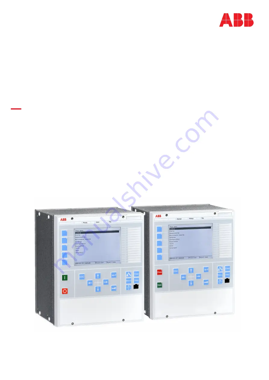
The ABB Relion REG650 is a cutting-edge protection and control relay ideal for various medium-voltage application settings. Simplify the commissioning process with the comprehensive commissioning manual available for free download from 88.208.23.73:8080. This manual provides step-by-step instructions to ensure effortless installation and configuration of the REG650, empowering users to utilize its full potential.
Share
Download


Reviews:
No comments
Related manuals for Relion REG650

REG650 ANSI
Brand: ABB Pages: 144

RELION RET670
Brand: ABB Pages: 240

100 Series
Brand: 3M Pages: 26

C Series
Brand: Eaton Pages: 8

850
Brand: GE Multilin Pages: 870

221
Brand: VAMP Pages: 136

SecoGear
Brand: GE Pages: 56

C170
Brand: Valex Pages: 6

M4000
Brand: K&K Pages: 10

WORKTUNES WIRELESS
Brand: 3M Pages: 23

M9700
Brand: K&K Pages: 9

ZEN
Brand: Kask Pages: 64

SE-SR2
Brand: Datalogic Pages: 16

LARYVOX TAPE
Brand: Fahl Pages: 4

D-86651
Brand: Hama Pages: 8

SENTINEL
Brand: I-Gard Pages: 12

90287
Brand: P+P Pages: 7

H-4618
Brand: U-Line Pages: 6


