


Ensure that the maximum continuous current in an IED does not exceed four times its rated
value, if the measurement of the operating characteristics runs under constant voltage
conditions.
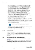
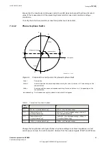
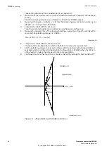
To verify the mho characteristic, at least two points must be tested.
7.4.1.2
Phase-to-phase faults
GUID-A5AE490E-FBEB-4B60-9F6B-80883260D87E v1
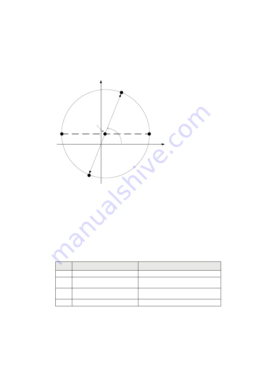
jX
R
Ohm/phase
ImpedanceAng
ZxFwd
ZxRev
P1
P2
P3
P4
Midpoint of circle
IEC09000173_1_en.vsd
IEC09000173 V1 EN-US
Figure 9:
Proposed four test points for phase-to-phase fault
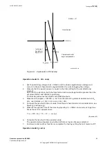
Label
Description
ZxFwd
Forward positive sequence impedance setting for zone x (where x is 1- 3 depending on the
zone selected).
ZxRev
Reverse positive sequence impedance setting for zone x (where x is 1- 3 depending on the
zone selected).
ImpedanceAng The Impedance angle for phase-to-phase fault in degrees.
Table 3:
Test points for phase-to-phase
Test
points
X
R
P1
ZxFwd · sin(ImpedanceAng)
ZxFwd · cos(ImpedanceAng)
P2
(ZxFwd-ZxRev)/2 ·
sin(ImpedanceAng)
ZxFwd/2 · (1+cos(Impeda ZxRev/2 ·
(1-cos(ImpedanceAng)
P3
(ZxFwd-ZxRev)/2 ·
sin(ImpedanceAng)
-ZxFwd/2 · (1-cos(ImpedanceAng) -ZxRev/2 ·
(1+cos(ImpedanceAng)
P4
-ZxRev · sin(ImpedanceAng)
-ZxRev · cos(ImpedanceAng)
Change the magnitude and angle of phase-to-phase voltage to achieve impedances at test
points p1, p2 and p3. For each test point, observe that the output signals, START and STZx are
1MRK 502 035-UEN A
Section 7
Testing functionality
Generator protection REG650
43
Commissioning manual
© Copyright 2011 ABB. All rights reserved


