


1.
Connect the test set for injection of three-phase currents to the appropriate current
terminals of the IED.
2.
Go to Main menu/Settings/IED Settings/Current/NS2PTOC(46I2,2I2>)/1:NS2PTOC/
General and make sure that the function is enabled, that is
Operation is set to On.
3.
Inject current into IEDs in such a way that negative sequence component is created and
then verify that negative sequence component of the injected currents is calculated
correctly by the function. See example below for 1 A rated current transformer.
4.
Inject pure negative sequence current, that is, phase currents with exactly same
magnitude, reversed sequence and exactly 120° phase displaced into the IED with an
initial value below negative sequence current start level. No output signals should be
activated.
Note: If it is difficult to obtain pure negative sequence current for the secondary injection
test, a current corresponding to the two phase short-circuit condition can be used. A two
phase short-circuit gives a negative sequence current of a magnitude: magnitude =
(1/√3) · fault current.
5.
Increase the injected current and note the value at which the step 1 of the function
operates. Start signal ST1 must be activated when amplitude of the negative sequence
current lies slightly above the start level
I2-1>. Corresponding trip signals TR1 and TRIP is
activated after the pre-set time delay has expired.
Note: Block or disable operation of step 2 when testing step 1 if the injected current
activates the step 2.
6.
Decrease the current slowly and note the reset value.
7.
Connect a trip output contact to a timer.
8.
Set the current to 200 % of the start level of the step 1, switch on the current and check
the definite time delay for trip signals TR1 and TRIP. Once the measured negative
sequence current exceeds the set atart level
I2-1>, the settable definite timer t1 starts to
count and trip signals is released after the set time delay has elapsed. The same test
must be carried out to check the accuracy of definite time delay for ALARM signal.
Note: The output ALARM is operated by START signal.
9.
If inverse time is selected the trip signals TR1 and TRIP operates after a time
corresponding to the formula:
t s
I
[ ]
(
)
=
− >
⋅
1
2 1
100
2
2
Multiple of Start
K
K
This means that if current jumps from 0 to 2 times start and negative sequence
capability value of generator
K1 is set to 10 sec and current start level I2-1> is set to 10%
of rated generator current, then TR1 and TRIP signals operates at time equal to 250 sec ±
tolerance.
10. Repeat the above-described tests for the step 2 of the function excluding the inverse
time testing.
11.
Finally check that start and trip information is stored in the event menu.
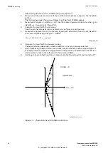
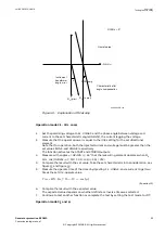
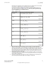
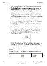
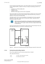
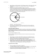
Example
If CT ratios
CTprim/CTsec for all three phases are 1000 and IBase is set to 1000 A, than the
following secondary currents shall be applied.
IL1
Ampl = 1.1 A
Angl = 15 deg
IL2
Ampl = 0.6 A
Angl = 97 deg
IL3
Ampl = 1.3 A
Angl = -135 deg
Section 7
1MRK 502 035-UEN A
Testing functionality
64
Generator protection REG650
Commissioning manual
© Copyright 2011 ABB. All rights reserved


