


4.2.4
Setting of voltage channels
As the IED uses primary system quantities the main VT ratios must be known to the
IED. This is done by setting the two parameters
VTsec
and
VTprim
for each voltage
channel. The phase-to-phase value can be used even if each channel is connected to a
phase-to-earth voltage from the VT.
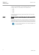
4.2.4.1
Example
Consider a VT with the following data:
132
110
3
3
kV
V
EQUATION2016 V1 EN
(Equation 1)
The following setting should be used:
VTprim=132
(value in kV)
VTsec=110
(value
in V)
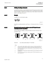
4.2.4.2
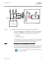
Examples how to connect, configure and set VT inputs for most
commonly used VT connections
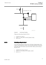
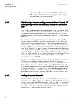
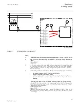
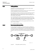
Figure
defines the marking of voltage transformer terminals commonly used
around the world.
A
(H1)
B
(H2)
b
(X2)
a
(X1)
A
(H1)
N
(H2)
n
(X2)
a
(X1)
b)
c)
A
(H1)
N
(H2)
dn
(X2)
da
(X1)
d)
U
Pri
+
+
U
Sec
a)
en06000591.vsd
IEC06000591 V1 EN
Figure 29:
Commonly used markings of VT terminals
Where:
a)
is the symbol and terminal marking used in this document. Terminals marked with a dot
indicate the primary and secondary winding terminals with the same (positive) polarity
b)
is the equivalent symbol and terminal marking used by IEC (ANSI) standard for phase-to-
earth connected VTs
c)
is the equivalent symbol and terminal marking used by IEC (ANSI) standard for open delta
connected VTs
d)
is the equivalent symbol and terminal marking used by IEC (ANSI) standard for phase-to-
phase connected VTs
1MRK 505 291-UEN A
Section 4
Analog inputs
71
Application manual
Summary of Contents for Relion REQ650
Page 1: ...Relion 650 series Breaker protection REQ650 Application manual ...
Page 2: ......
Page 20: ...14 ...
Page 26: ...20 ...
Page 48: ...42 ...
Page 82: ...76 ...
Page 90: ...84 ...
Page 160: ...154 ...
Page 178: ...172 ...
Page 264: ...258 ...
Page 288: ...282 ...
Page 302: ...296 ...
Page 330: ...324 ...
Page 338: ...332 ...
Page 339: ...333 ...


