


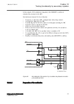

10.8.2
Fuse failure supervision FRWSPVC
GUID-EBA43544-8FC0-4648-8064-F72211FD8520 v2
Prepare the IED for verification of settings outlined in Section
.
Values of the logical signals for FRWSPVC are available on the local HMI under
Main menu/Tests/Function status/Secondary system supervision/
FuseFailure(U>/I<)/FRWSPVC(U>/I<):x
, where x = instance number.
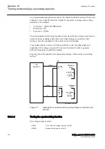
The verification is divided in two main parts. The first part is common to all fuse
failure supervision options, and checks that binary inputs and outputs operate as
expected according to actual configuration. In the second part the relevant set
operate values are measured.
10.8.2.1
Checking that the binary inputs and outputs operate as expected
GUID-D348A922-B7E3-4089-B92E-9BE9268A7A24 v2
1.
Simulate normal operating conditions with the two-phase currents in phase
with their corresponding phase voltages and with all of them equal to their
rated values.
2.
Connect the nominal dc voltage to the DISCPOS binary input.
•
The signal BLKU should appear with almost no time delay.
•
The signal BLKZ should not appear on the IED.
•
Only the distance protection function can operate.
•
Undervoltage-dependent functions must not operate.
3.
Disconnect the dc voltage from the DISCPOS binary input terminal.
4.
Connect the nominal dc voltage to the MCBOP binary input.
•
The BLKUand BLKZ signals should appear without any time delay.
•
All undervoltage-dependent functions must be blocked.
5.
Disconnect the dc voltage from the MCBOP binary input terminal.
6.
Disconnect one of the phase voltages and observe the logical output signals
on the binary outputs of the IED. BLKU and BLKZ signals should appear
simultaneously.
10.8.2.2
Measuring the operate value for the dead line detection function
GUID-0CF1BA07-57BF-410F-BE8F-C3CDA5635E36 v2
1.
Apply two-phase voltages with their rated value and zero currents.
2.
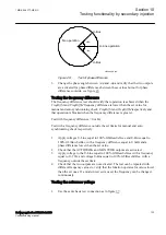
Decrease the measured voltage in both phases until the DLD2PH signal
appears.
3.
This is the point at which the dead line condition is detected. Check the value
of the decreased voltage with the set value
UDLD<
(
UDLD<
is in percent of
the base voltage
UBase
).
1MRK 506 377-UEN C
Section 10
Testing functionality by secondary injection
Railway application RER670 2.2 IEC
125
Commissioning manual
Summary of Contents for RELION RER670
Page 1: ...RELION 670 SERIES Railway application RER670 Version 2 2 IEC Commissioning manual...
Page 2: ......
Page 26: ...20...
Page 54: ...48...
Page 58: ...52...
Page 62: ...56...
Page 80: ...74...
Page 188: ...182...
Page 194: ...188...
Page 204: ...198...
Page 214: ...208...
Page 215: ...209...


