
4.
Apply two-phase currents with their rated value and zero voltages.
5.
Decrease the measured current in both phases until the DLD2PH signal
appears.
6.
This is the point at which the dead line condition is detected. Check the value
of the decreased current with the set value
IDLD<
(
IDLD<
is in percent of
the base current
IBase
).
10.8.2.3
Checking the operation of the du/dt and di/dt based function
GUID-102B7334-0E33-45AE-A353-869ED527770A v2
Check the operation of the du/dt and di/dt based function if included in the IED.
1.
Simulate normal operating conditions with the two-phase currents in phase
with their corresponding phase voltages and with all of them equal to their
rated values.
2.
Change the voltages and currents in all phases simultaneously.
The voltage change must be higher than the set value
DU>
and the current
change must be lower than the set value
DI<
.
The BLKU and BLKZ signals appear without any time delay.
3.
Apply normal conditions as in step
The BLKU and BLKZ signals should reset, if activated, see step
.
4.
Change the voltages and currents in all phases simultaneously.
The voltage change must be higher than the set value
DU>
and the current
change must be higher than the set value
DI<
.
The BLKU and BLKZ signals should not appear.
5.
Repeat step
.
6.
Connect the rated voltages in all phases and feed a current below the operate
level in all phases.
7.
Keep the current constant. Disconnect the voltage in both two phases
simultaneously.
The BLKU and BLKZ signals should not appear.
10.8.2.4
Completing the test
GUID-E265B56C-4064-40DD-A39C-26CBE54F6227 v1
Continue to test another function or end the test by changing the
TestMode
setting
to
Off
. Restore connections and settings to their original values, if they were
changed for testing purposes.
10.8.3
Voltage based delta supervision DELVSPVC
GUID-FBFEC9C5-1B76-4688-A00D-9EEB33326966 v1
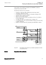
Prepare the IED for verification of settings outlined in Section
10.8.3.1
Verifying the signals and settings
GUID-B05EE7E5-2360-4036-991A-00747C47A625 v2
Make sure that the function is connected to SMAI function with U2P signal.
Section 10
1MRK 506 377-UEN C
Testing functionality by secondary injection
126
Railway application RER670 2.2 IEC
Commissioning manual
Summary of Contents for RELION RER670
Page 1: ...RELION 670 SERIES Railway application RER670 Version 2 2 IEC Commissioning manual...
Page 2: ......
Page 26: ...20...
Page 54: ...48...
Page 58: ...52...
Page 62: ...56...
Page 80: ...74...
Page 188: ...182...
Page 194: ...188...
Page 204: ...198...
Page 214: ...208...
Page 215: ...209...