


At commissioning and periodical checks, the functions shall be tested with the used
settings. To test a specific function, it might be necessary to change some setting
parameters, for example:
•
AutoEnerg
=
Off
/
DLLB
/
DBLL
/
Both
•
ManEnerg
=
Off
•
Operation
=
Off
/
On
The tests explained in the test procedures below describe the settings, which can be
used as references during testing before the final settings are specified. After
testing, restore the equipment to the normal or desired settings.
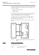
A secondary injection test set with the possibility to alter the phase angle and
amplitude of the voltage is needed. The test set must also be able to generate
different frequencies on different outputs.
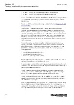
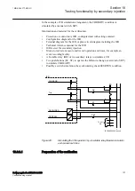
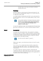
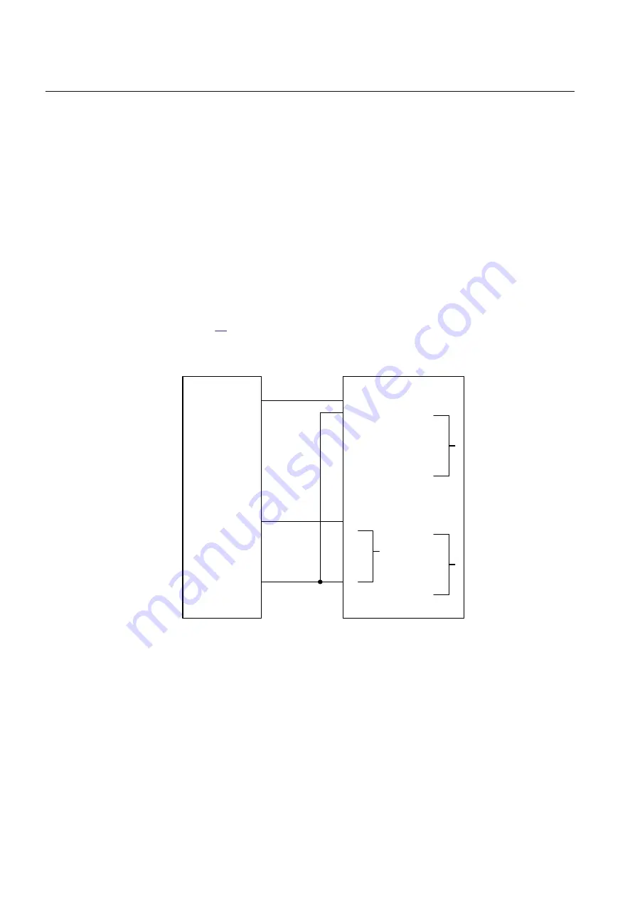
shows the general test connection principle, which can be used during
testing.
Test
equipment
UMeasure
Ph/Ph
U-Bus
U-Line
N
IED
U2PBB
N
UL1
UL2
N
Input Phase
L1,L2
Pos.Seq.
UMeasure
Ph/Ph
Input Phase
L1,L2
Pos.Seq.
U2PLN
IEC15000310-2-en.vsdx
IEC15000310 V2 EN-US
Figure 27:
General test connection with two-phase voltage connected to the
line side
10.9.1.1
Testing the synchronizing function
M2377-21 v8
The voltage inputs used are:
U2PLN
UL1 or UL2 line voltage inputs on the IED
U2PBB
Busbar voltage input on the IED
Section 10
1MRK 506 377-UEN C
Testing functionality by secondary injection
130
Railway application RER670 2.2 IEC
Commissioning manual
Summary of Contents for RELION RER670
Page 1: ...RELION 670 SERIES Railway application RER670 Version 2 2 IEC Commissioning manual...
Page 2: ......
Page 26: ...20...
Page 54: ...48...
Page 58: ...52...
Page 62: ...56...
Page 80: ...74...
Page 188: ...182...
Page 194: ...188...
Page 204: ...198...
Page 214: ...208...
Page 215: ...209...


