


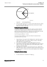


The voltage difference between the voltage connected to U-Bus and U-Line
should be 0%, so that the AUTOSYOK and MANSYOK outputs are activated
first.
2.
Change the U-Line voltage connection to U-Line2 without changing the
setting on the local HMI. Check that the two outputs are not activated.
10.9.1.3
Testing the energizing check
M2377-262 v6
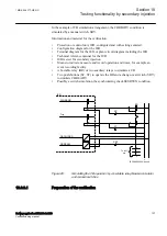
During the test of the energizing check function for a single bay arrangement, these
voltage inputs are used:
U-Line
UL1 or UL2 line voltage inputs on the IED
U-Bus
Bus voltage input on the IED
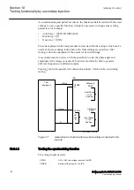
General
M2377-271 v6
When testing the energizing check function for the applicable bus, arrangement
shall be done for the energizing check functions. The voltage is selected by
activation of different inputs in the voltage selection logic.
Live voltage level is fixed to 80%
UBase
and dead voltage level to fixed 40%
UBase
.
The test shall be performed according to the settings for the station. Test the
alternatives below that are applicable.
Testing the dead line live bus (DLLB)
M2377-276 v7
The test should verify that the energizing check function operates for a low voltage
on the U-Line and for a high voltage on the U-Bus. This corresponds to the
energizing of a dead line to a live bus.
1.
Apply a single-phase voltage 100%
GblBaseSelBus
to the U-Bus, and a
single-phase voltage 30%
GblBaseSelLine
to the U-Line.
2.
Check that the AUTOENOK and MANENOK outputs are activated after set
tAutoEnerg
respectively
tManEnerg
.
3.
Increase the U-Line to 60%
GblBaseSelLine
and U-Bus to be equal to 100%
GblBaseSelBus
. The outputs should not be activated.
4.
The test can be repeated with different values on the U-Bus and the U-Line.
Testing the dead bus live line (DBLL)
M2377-289 v8
The test should verify that the energizing check function operates for a low voltage
on the U-Bus and for a high voltage on the U-Line. This corresponds to an
energizing of a dead bus to a live line.
Section 10
1MRK 506 377-UEN C
Testing functionality by secondary injection
134
Railway application RER670 2.2 IEC
Commissioning manual
Summary of Contents for RELION RER670
Page 1: ...RELION 670 SERIES Railway application RER670 Version 2 2 IEC Commissioning manual...
Page 2: ......
Page 26: ...20...
Page 54: ...48...
Page 58: ...52...
Page 62: ...56...
Page 80: ...74...
Page 188: ...182...
Page 194: ...188...
Page 204: ...198...
Page 214: ...208...
Page 215: ...209...


