


1.
Verify the settings
AutoEnerg
or
ManEnerg
to be
DBLL
.
2.
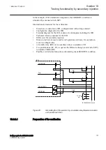
Apply a single-phase voltage of 30%
GblBaseSelBus
to the U-Bus and a
single-phase voltage of 100%
GblBaseSelLine
to the U-Line.
3.
Check that the AUTOENOK and MANENOK outputs are activated after set
tAutoEnerg
respectively
tManEnerg
.
4.
Decrease the U-Line to 60%
GblBaseSelLine
and keep the U-Bus equal to
30%
GblBaseSelBus
. The outputs should not be activated.
5.
The test can be repeated with different values on the U-Bus and the U-Line.
Testing both directions (DLLB or DBLL)
M2377-306 v7
1.
Verify the local HMI settings
AutoEnerg
or
ManEnerg
to be
Both
.
2.
Apply a single-phase voltage of 30%
GblBaseSelLine
to the U-Line and a
single-phase voltage of 100%
GblBaseSelBus
to the U-Bus.
3.
Check that the AUTOENOK and MANENOK outputs are activated after set
tAutoEnerg
respectively
tManEnerg
.
4.
Change the connection so that the U-Line is equal to100%
GblBaseSelLine
and the U-Bus is equal to 30%
GblBaseSelBus
. The outputs should still be
activated.
5.
The test can be repeated with different values on the U-Bus and the U-Line.
Testing the dead bus dead line (DBDL)
M2377-323 v8
The test should verify that the energizing check function operates for a low voltage
on both the U-Bus and the U-Line, that is, closing of the breaker in a non-energized
system. Test is valid only when this function is used.
1.
Verify the local HMI setting
AutoEnerg
to be
Off
and
ManEnerg
to be
DBLL
.
2.
Set the parameter
ManEnergDBDL
to
On
.
3.
Apply a single-phase voltage of 30%
GblBaseSelBus
to the U-Bus and a
single-phase voltage of 30%
GblBaseSelLine
to the U-Line.
4.
Check that the MANENOK output is activated after set
tManEnerg
.
5.
Increase the U-Bus to 80%
GblBaseSelBus
and keep the U-Line equal to 30%
GblBaseSelLine
. The outputs should not be activated.
6.
Repeat the test with
ManEnerg
set to
DLLB
with different values on the U-
Bus and the U-Line voltage.
10.9.1.4
Completing the test
M2377-1042 v5
continue to test another function or end the test by changing the
TESTMODE
setting to
Off
. Restore connections and settings to their original values, if they were
changed for testing purposes.
10.9.2
Autoreclosing for railway system SMBRREC
GUID-591C27E8-AB95-46E0-AA2C-6D7222548349 v2
The verification of the auto recloser function for railway system consists of two
parts:
1MRK 506 377-UEN C
Section 10
Testing functionality by secondary injection
Railway application RER670 2.2 IEC
135
Commissioning manual
Summary of Contents for RELION RER670
Page 1: ...RELION 670 SERIES Railway application RER670 Version 2 2 IEC Commissioning manual...
Page 2: ......
Page 26: ...20...
Page 54: ...48...
Page 58: ...52...
Page 62: ...56...
Page 80: ...74...
Page 188: ...182...
Page 194: ...188...
Page 204: ...198...
Page 214: ...208...
Page 215: ...209...