


intended response of the voltage control function for different
secondary injection tests.
Terminology
The busbar voltage U
B
is a shorter notation for the measured voltages UL1, UL2,
UL3 or Uij, where Uij is the phase-phase voltage, Uij = Ui -Uj, or Ui, where Ui is
one single-phase-to-earth voltage.
I
L
is a shorter notation for the measured load current; it is to be used instead of the
three-phase quantities IL1, IL2, IL3 or the two-phase quantities Ii and Ij, or single-
phase current Ii.
Also note that for simplicity, the Parameter Setting menu structures
included in the following procedure are referred to universally as
VCP1, for example,
Main menu/Settings/IED Settings/Control/
TransformerVoltageControl(ATCC,90)/TR1ATCC:x/
TR8ATCC:x/Time/t1 and t2l
.
For cases where single-mode voltage control is implemented, the Parameter Setting
menu structure includes TR1ATCC:1 instead of the parallel designator TR8ATCC:
1.
10.9.4.1
Secondary test
SEMOD175185-145 v5
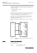
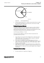
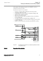
The voltage control function performs basic voltage regulation by comparing a
calculated load voltage (U
L
) against a voltage range defined by setting
UDeadband
(with upper and lower limits U2 and U1 respectively). The calculated load voltage
U
L
represents the secondary transformer bus voltage U
B
adjusted for Load drop
compensation (LDC) where enabled in settings.
Note that when LDC is disabled, U
B
equals U
L
.
When the load voltage U
L
stays within the interval between U1 and U2, no action
will be taken.
If U
L
< U1 or U
L
> U2, a command timer will start, which is constant time or
inverse time defined by setting
t1
and
t1Use
. The command timer will operate
while the measured voltage stays outside the inner deadband (defined by setting
UDeadbandInner
).
If U
L
remains outside of the voltage range defined by
UDeadband
and the
command timer expires, the voltage control will execute a raise or lower command
to the transformer tap changer. This command sequence will be repeated until U
L
is
brought back within the inner deadband range.
1MRK 506 377-UEN C
Section 10
Testing functionality by secondary injection
Railway application RER670 2.2 IEC
143
Commissioning manual
Summary of Contents for RELION RER670
Page 1: ...RELION 670 SERIES Railway application RER670 Version 2 2 IEC Commissioning manual...
Page 2: ......
Page 26: ...20...
Page 54: ...48...
Page 58: ...52...
Page 62: ...56...
Page 80: ...74...
Page 188: ...182...
Page 194: ...188...
Page 204: ...198...
Page 214: ...208...
Page 215: ...209...


