


raise/lower commands detected from the binary output mapped in the Signal
Matrix.
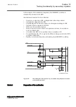
The voltage injection equal to
USet
is required for both
transformers during this test.
12. Confirm that a tap change command is issued from the voltage control
function to compensate for the circulating current.
13. Injected currents can be reversed such that the direction of calculated
circulating currents change polarity, which will cause a lower command for
Transformer 2 and a raise command for Transformer 1.
Circulating current limit
SEMOD175185-841 v6
1.
Confirm that
OperationPAR
is set to
CC
for each transformer in the parallel
group.
2.
Confirm that
OperCCBlock
is set to
On
for each transformer in the parallel
group.
3.
Review the setting for
CircCurrLimit
.
4.
Review the setting for
CircCurrBk
to confirm whether a circulating current
limit will result in an
Alarm
state,
Auto Block
or
Auto&Man Block
of the
automatic voltage control for tap changer, for parallel control function
TR8ATCC.
5.
Inject a voltage U
B
equal to
USet
for each transformer.
6.
Inject a load current for Transformer 1 that is equal to rated load current
I2Base
and a load current for Transformer 2 that is 1% less than (
I2Base
–
(
I2Base
· CircCurrLimit))
7.
Confirm that the automatic voltage control for tap changer, for parallel
control function TR8ATCC responds in accordance with the setting for
CircCurrBk
. Alarm and blocking conditions can be confirmed through
interrogation of the event menu or the control menu on the local HMI.
VTmismatch during parallel operation
SEMOD175185-859 v4
1.
Confirm that
OperationPAR
is set to
MF
for each transformer in the parallel
group.
2.
Review the setting for
VTmismatch
and
tVTmismatch
.
3.
Inject a voltage U
B
equal to
USet
for Transformer 1 and a voltage less than
(
USet
– (
VTmismatch
·
USet
)) for Transformer 2.
4.
This condition should result in a
VTmismatch
which will mutually block the
operation of the automatic voltage control for tap changer, parallel control
function TR8ATCC for all transformers connected in the parallel group,
which can be confirmed through interrogation of the local HMI.
5.
Confirm that the automatic voltage control for tap changer, parallel control
function TR8ATCC responds in accordance with the setting for
CircCurrBk
.
1MRK 506 377-UEN C
Section 10
Testing functionality by secondary injection
Railway application RER670 2.2 IEC
151
Commissioning manual
Summary of Contents for RELION RER670
Page 1: ...RELION 670 SERIES Railway application RER670 Version 2 2 IEC Commissioning manual...
Page 2: ......
Page 26: ...20...
Page 54: ...48...
Page 58: ...52...
Page 62: ...56...
Page 80: ...74...
Page 188: ...182...
Page 194: ...188...
Page 204: ...198...
Page 214: ...208...
Page 215: ...209...


