


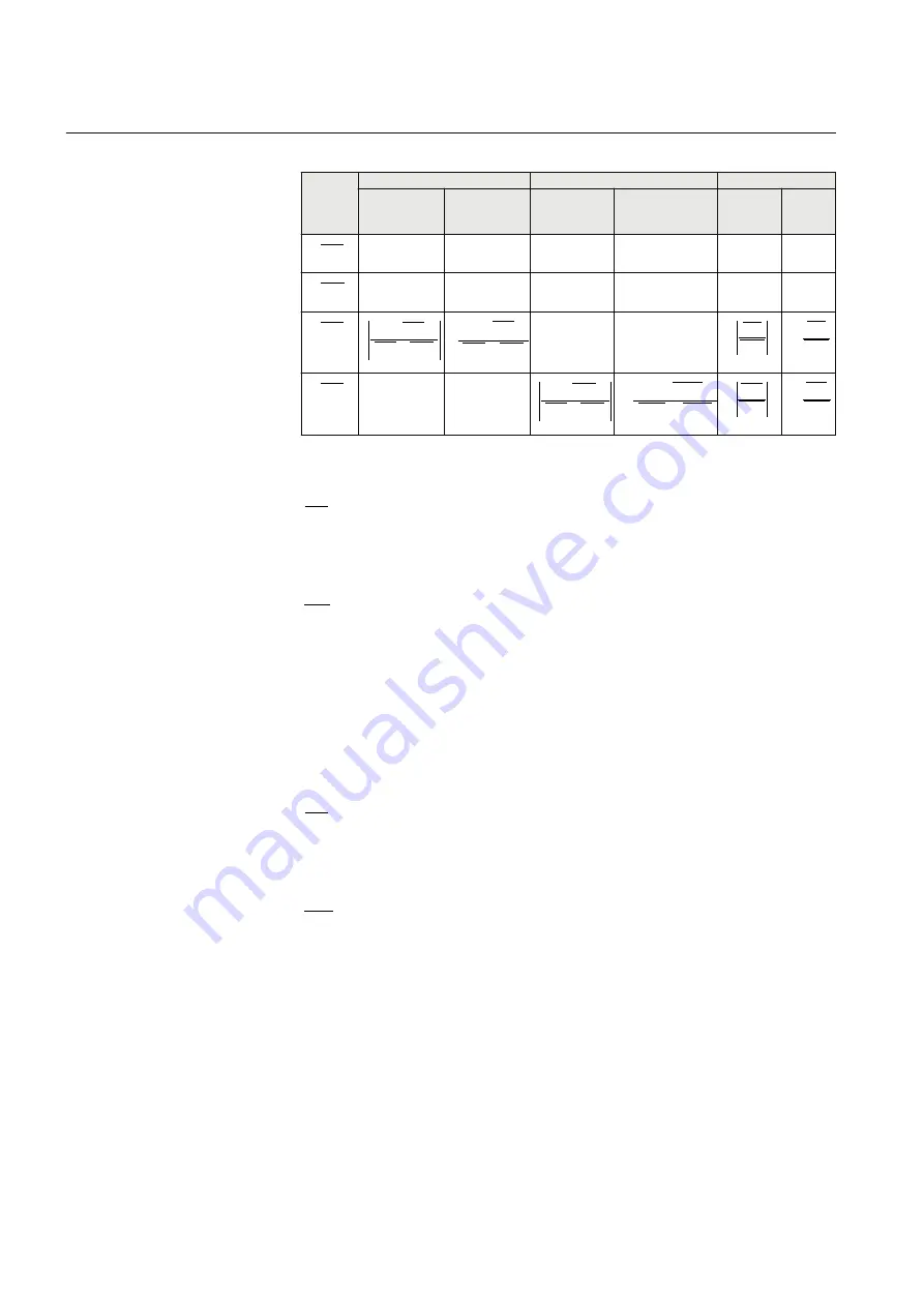
Table 27:
Fault voltage and current for L1N / L2N / L1L2 faults
L1E
L2E
L1L2
Signal
Magnitude
(Volt or
Amps)
Angle
(Degrees)
Magnitude
(Volt or
Amps)
Angle (Degrees) Magnitud
e (Volt or
Amps)
Angle
(Degree
s)
1
UL
IECEQUATIO
N15084 V1
EN-US
55
0
55
0
55
0
2
UL
IECEQUATIO
N15085 V1
EN-US
55
180
55
180
55
180
1
IL
IECEQUATIO
N15086 V1
EN-US
0
1
1
2
ZA
ZA
UL
IECEQUATION15088 V1
EN-US
0
1
1
2
ZA
ZA
UL
IECEQUATION15095 V1
EN-US
0
0
1
1
ZA
UL
IECEQUATION1
5090 V1 EN-US
1
1
ZA
UL
IECEQUATIO
N15121 V1
EN-US
2
IL
IECEQUATIO
N15087 V1
EN-US
0
180
0
1
2
2
ZA
ZA
UL
IECEQUATION15089
V1 EN-US
0
1
2
2
ZA
ZA
UL
IECEQUATION15099 V1 EN-
US
1
2
ZA
UL
IECEQUATION1
5091 V1 EN-US
1
2
ZA
UL
IECEQUATIO
N15122 V1
EN-US
Where:
1
ZA
= Positive sequence impedance from the point of measurement until the
fault point.
This can be derived from:
1
1
1
XA
j
RA
ZA
IECEQUATION15093 V1 EN-US
(Equation 20)
Where:
XLj
p
XLi
XA
RLj
p
RLi
RA
tion
fault
i
tion
fault
i
1
sec
1
1
sec
1
1
1
IECEQUATION15094 V1 EN-US
(Equation 21)
0
ZA
= Positive sequence impedance from the point of measurement until the
fault point.
This can be derived from,
0
0
0
XA
j
RA
ZA
IECEQUATION15097 V1 EN-US
(Equation 22)
Where:
XEOverXLj
XLj
p
XEOverXLi
XLi
XA
REOverRLj
RLj
p
REOverRLi
RLi
RA
tion
fault
i
tion
fault
i
2
2
0
2
2
0
1
sec
1
1
sec
1
IECEQUATION15098 V1 EN-US
(Equation 23)
Section 10
1MRK 506 377-UEN C
Testing functionality by secondary injection
172
Railway application RER670 2.2 IEC
Commissioning manual
Summary of Contents for RELION RER670
Page 1: ...RELION 670 SERIES Railway application RER670 Version 2 2 IEC Commissioning manual...
Page 2: ......
Page 26: ...20...
Page 54: ...48...
Page 58: ...52...
Page 62: ...56...
Page 80: ...74...
Page 188: ...182...
Page 194: ...188...
Page 204: ...198...
Page 214: ...208...
Page 215: ...209...


