


Test the correct functionality by simulating different kind of faults. Also check that
sent and received data is correctly transmitted and read.
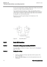
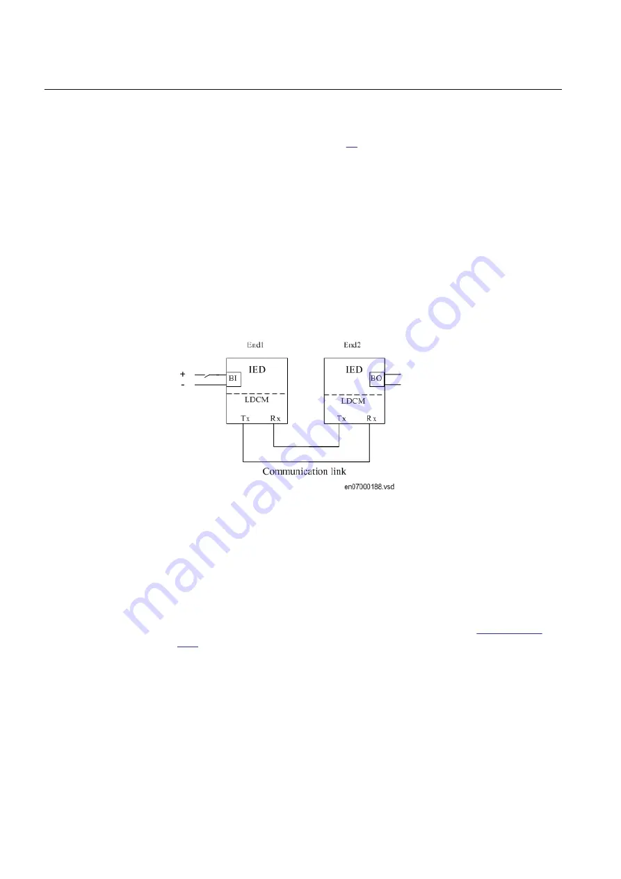
A test connection is shown in figure
. A binary input signal (BI) at End1 is
configured to be transferred through the communication link to End2. At End2 the
received signal is configured to control a binary output (BO). Check at End2 that
the BI signal is received and the BO operates.
Repeat the test for all the signals configured to be transmitted over the
communication link.
IEC07000188 V1 EN-US
Figure 32:
Test of RTC with I/O
10.16
Basic IED functions
SEMOD52026-1 v1
10.16.1
Parameter setting group handling SETGRPS
M11369-2 v4
Prepare the IED for verification of settings as outlined in section
10.16.1.1
Verifying the settings
M11369-4 v5
1.
Check the configuration of binary inputs that control the selection of the
active setting group.
2.
Browse to the
ActiveGroup
menu to achieve information about the active
setting group.
Section 10
1MRK 506 377-UEN C
Testing functionality by secondary injection
180
Railway application RER670 2.2 IEC
Commissioning manual
Summary of Contents for RELION RER670
Page 1: ...RELION 670 SERIES Railway application RER670 Version 2 2 IEC Commissioning manual...
Page 2: ......
Page 26: ...20...
Page 54: ...48...
Page 58: ...52...
Page 62: ...56...
Page 80: ...74...
Page 188: ...182...
Page 194: ...188...
Page 204: ...198...
Page 214: ...208...
Page 215: ...209...