


IEC15000106-1-en.vsdx
~ Z
G
I>
I
F,e
R
G,I
R
G,c
V
NG
I
NG
IEC15000106 V1 EN-US
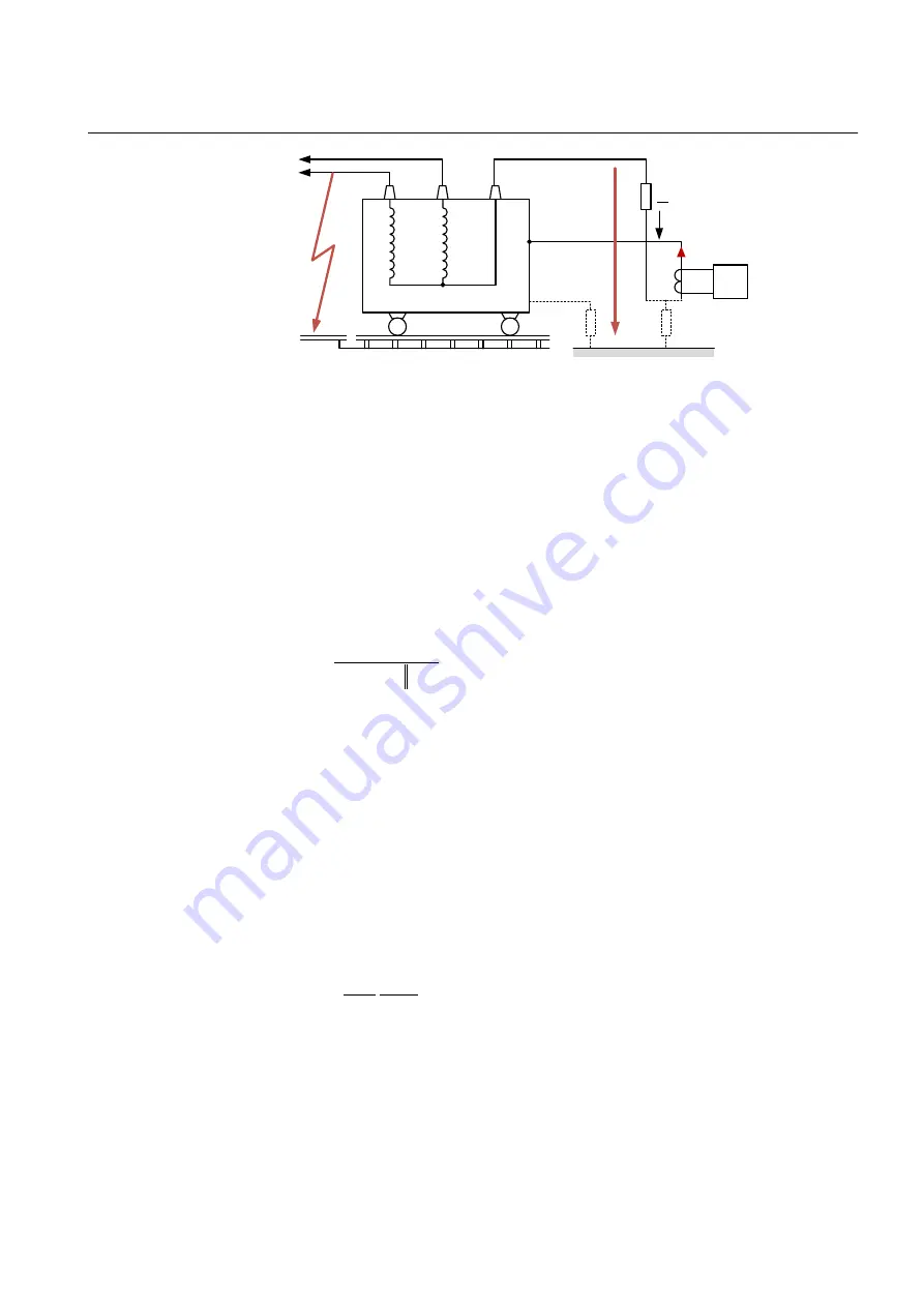
Figure 64:
Behaviour of ground fault protection during an external fault
where:
R
G,I
Leakage resistance of the tank
R
G,C
Ground contact resistance
Z
G
Neutral grounding impedance
I
NG
is described as:
I
G
C
G
G
NG
NG
R
R
Z
V
I
,
,
IECEQUATION051 V2 EN-US
(Equation 58)
I
Fe
R
G,I
is described as:
C
G
Fe
NG
I
G
Fe
R
I
I
R
I
,
,
)
(
IECEQUATION052 V2 EN-US
(Equation 59)
For
C
G
I
G
G
R
R
Z
,
,
,
IECEQUATION053 V2 EN-US
(Equation 60)
I
Fe
is described as:
I
G
C
G
G
NG
Fe
R
R
Z
V
I
,
,
IECEQUATION054 V2 EN-US
(Equation 61)
The current flow in case of an external phase to ground fault should not operate the
tank protection. Therefore, start value is set above the absolute value of this
current. In other words, the ratio of ground contact resistance R
G,C
to leakage
1MRK 506 375-UEN A
Section 8
Current protection
Railway application RER670 2.2 IEC
193
Application manual
Summary of Contents for RELION RER670
Page 1: ...RELION 670 SERIES Railway application RER670 Version 2 2 IEC Application manual ...
Page 2: ......
Page 22: ...16 ...
Page 48: ...42 ...
Page 70: ...64 ...
Page 80: ...74 ...
Page 100: ...94 ...
Page 210: ...204 ...
Page 364: ...358 ...
Page 384: ...378 ...
Page 468: ...462 ...
Page 494: ...488 ...
Page 504: ...498 ...
Page 505: ...499 ...


