


12.1.2.3
Energizing check
M12310-3 v12
The main purpose of the energizing check function is to facilitate the controlled re-
connection of disconnected lines and buses to energized buses and lines.
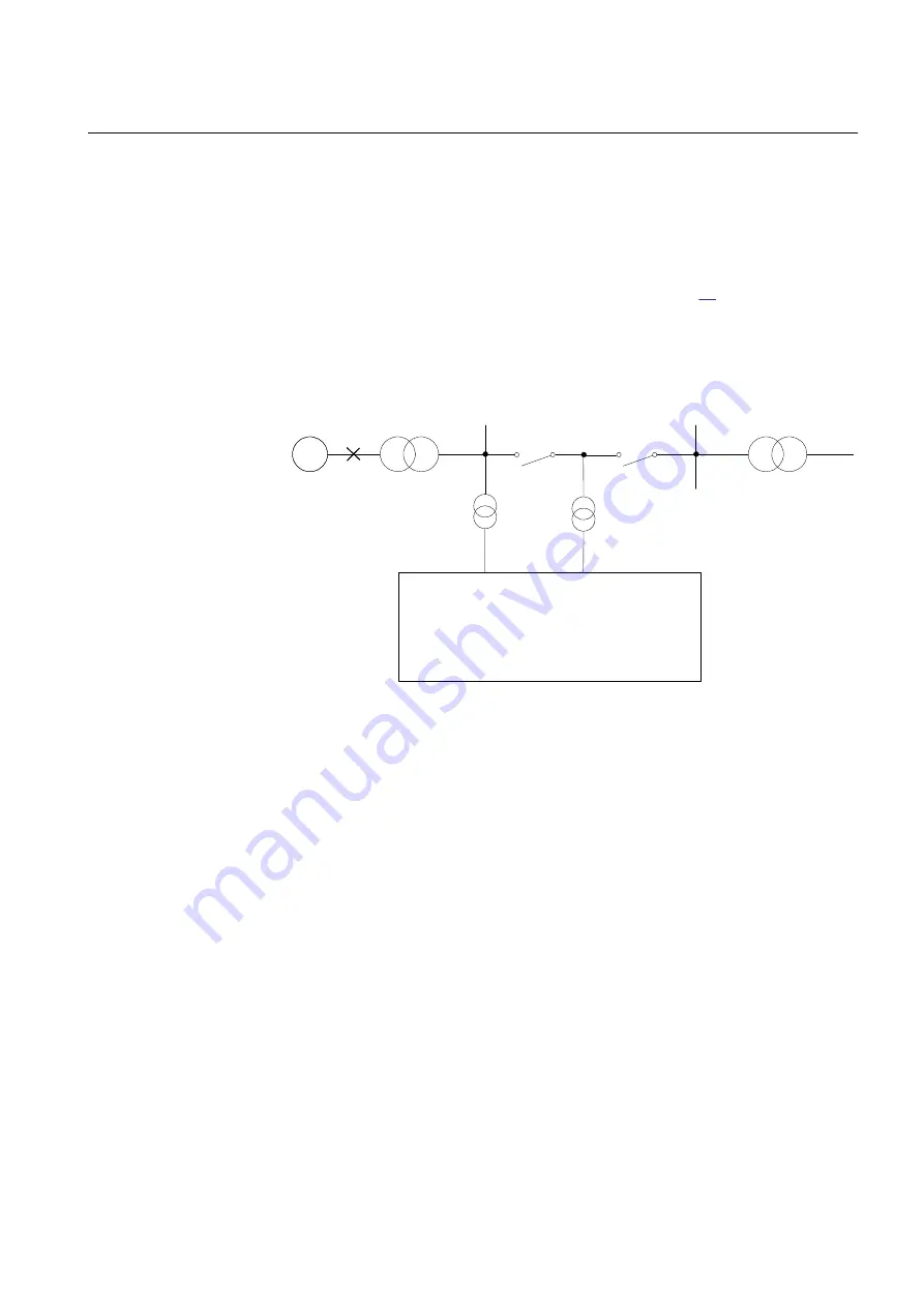
The energizing check function measures the bus and line voltages and compares
them to both high and low threshold values. The output is given only when the
actual measured conditions match the set conditions. Figure
substations, where one (1) is energized and the other (2) is not energized. The line
between CB A and CB B is energized (DLLB) from substation 1 via the circuit
breaker A and energization of station 2 is done by CB B energization check device
for that breaker DBLL. (or Both).
~
1
2
A
EnergizingCheck
UHighBusEnerg > 10 - 120 % of GblBaseSelBus
UHighLineEnerg > 10 - 120 % of GblBaseSelLine
ULowBusEnerg < 10 - 80 % of GblBaseSelBus
ULowLineEnerg < 10 - 80 % of GblBaseSelLine
UMaxEnerg < 50 - 180 % of GblBaseSelBus and/or
GblBaseSelLine
Line voltage
Bus voltage
IEC17000008-1-en.vsdx
B
IEC17000008 V1 EN-US
Figure 67:
Principle for the energizing check function
The energizing operation can operate in the dead line live bus (DLLB) direction,
dead bus live line (DBLL) direction, or in both directions over the circuit breaker.
Energizing from different directions can be different for automatic reclosing and
manual closing of the circuit breaker. For manual closing it is also possible to allow
closing when both sides of the breaker are dead, Dead Bus Dead Line (DBDL).
The equipment is considered energized (Live) if the voltage is above the set value
for
UHighBusEnerg
or
UHighLineEnerg
of the base voltages
GblBaseSelBus
and
GblBaseSelLine
, which are defined in the Global Base Value groups; in a similar
way, the equipment is considered non-energized (Dead) if the voltage is below the
set value for
ULowBusEnerg
or
ULowLineEnerg
of the respective Global Base
Value groups. A disconnected line can have a considerable potential due to factors
such as induction from a line running in parallel, or feeding via extinguishing
capacitors in the circuit breakers. This voltage can be as high as 50% or more of
the base voltage of the line. Normally, for breakers with single breaking elements
(<330 kV) the level is well below 30%.
When the energizing direction corresponds to the settings, the situation has to
remain constant for a certain period of time before the close signal is permitted.
1MRK 506 375-UEN A
Section 12
Control
Railway application RER670 2.2 IEC
215
Application manual
Summary of Contents for RELION RER670
Page 1: ...RELION 670 SERIES Railway application RER670 Version 2 2 IEC Application manual ...
Page 2: ......
Page 22: ...16 ...
Page 48: ...42 ...
Page 70: ...64 ...
Page 80: ...74 ...
Page 100: ...94 ...
Page 210: ...204 ...
Page 364: ...358 ...
Page 384: ...378 ...
Page 468: ...462 ...
Page 494: ...488 ...
Page 504: ...498 ...
Page 505: ...499 ...


