


TR1ATCC then compares this voltage with the set voltage,
USet
and decides which
action should be taken. To avoid unnecessary switching around the setpoint, a
deadband (degree of insensitivity) is introduced. The deadband is symmetrical
around
USet
, and it is arranged in such a way that there is an outer
and an inner deadband. Measured voltages outside the outer deadband start the
timer to initiate tap commands, whilst the sequence resets when the measured
voltage is once again back inside the inner deadband. One half of the outer
deadband is denoted ΔU. The setting of ΔU, setting
Udeadband
should be set to a
value near to the power transformer’s tap changer voltage step (typically 75–125%
of the tap changer step).
Voltage Magnitude
Umax
U
2
Uset
U
1
Umin
Ublock
0
Raise Cmd
*) Action in accordance with setting
Security Range
Lower Cmd
IEC06000489_2_en.vsd
D
D
U
U
D
U
in
D
U
in
*)
*)
*)
IEC06000489 V2 EN-US
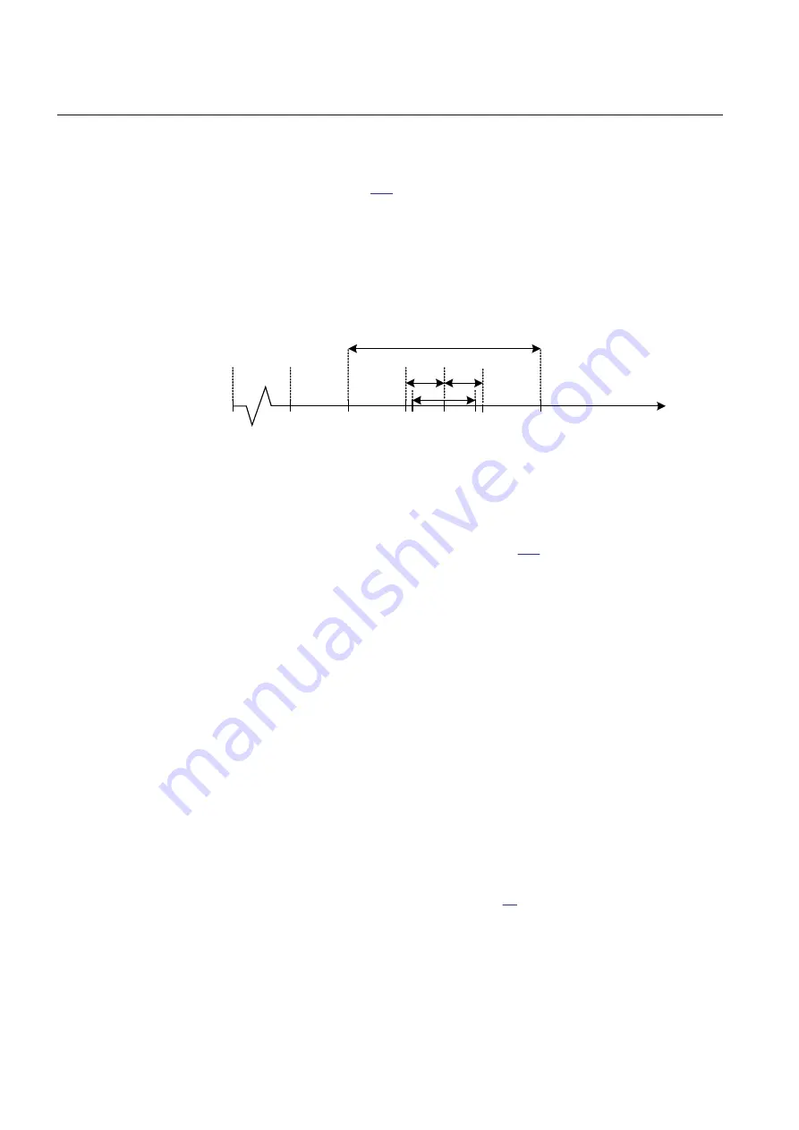
Figure 124:
Control actions on a voltage scale
During normal operating conditions the busbar voltage U
B
, stays within the outer
deadband (interval between U1 and U2 in figure
). In that case no actions will
be taken by TR1ATCC. However, if U
B
becomes smaller than U1, or greater than
U2, an appropriate raise or lower timer will start. The timer will run as long as the
measured voltage stays outside the inner deadband. If this condition persists longer
than the preset time delay, TR1ATCC will initiate that the appropriate ULOWER
or URAISE command will be sent from TCMYLTC or TCLYLTC function block
to the transformer tap changer. If necessary, the procedure will be repeated until the
magnitude of the busbar voltage again falls within the inner deadband. One half of
the inner deadband is denoted ΔU
in
. The inner deadband ΔU
in
, setting
UDeadbandInner
should be set to a value smaller than ΔU. It is recommended to
set the inner deadband to 25-70% of the ΔU value.
This way of working is used by TR1ATCC while the busbar voltage is within the
security range defined by settings
Umin
and
Umax
.
A situation where U
B
falls outside this range will be regarded as an abnormal
situation.
When U
B
falls below setting
Ublock
, or alternatively, falls below setting
Umin
but
still above
Ublock
, or rises above
Umax
, actions will be taken in accordance with
settings for blocking conditions (refer to table
).
If the busbar voltage rises above
Umax
, TR1ATCC can initiate one or more fast
step down commands (ULOWER commands) in order to bring the voltage back
into the security range (settings
Umin
, and
Umax
). The fast step down function
Section 12
1MRK 506 375-UEN A
Control
292
Railway application RER670 2.2 IEC
Application manual
Summary of Contents for RELION RER670
Page 1: ...RELION 670 SERIES Railway application RER670 Version 2 2 IEC Application manual ...
Page 2: ......
Page 22: ...16 ...
Page 48: ...42 ...
Page 70: ...64 ...
Page 80: ...74 ...
Page 100: ...94 ...
Page 210: ...204 ...
Page 364: ...358 ...
Page 384: ...378 ...
Page 468: ...462 ...
Page 494: ...488 ...
Page 504: ...498 ...
Page 505: ...499 ...


