


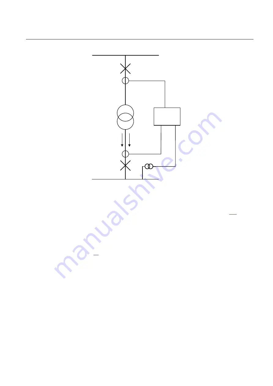
110kV Busbar
200/1
15kV Busbar
600/5
P
Q
8,0 MVA
110/15kV
UL1 & UL2
IEC16000125-1-en.vsdx
IED
15/0,1
kV
IEC16000125 V1 EN-US
Figure 161:
Single line diagram for transformer application
In order to measure the active and reactive power as indicated in figure
, it is
necessary to do the following:
1. Set correctly all CT and VT and phase angle reference channel
PhaseAngleRef
data using PCM600 for analog input channels
2. Connect, in PCM600, measurement function to LV side CT & VT inputs
3. Set the setting parameters for relevant Measurement function as shown in table
The power P&Q measurement is needed towards busbar (not towards IED, as
default). Proper inversion of current should be done in SMAI block for the current
channels in order to get correct direction of P&Q. Note that, in such case this
SMAI block shall only be used for the measurement functions.
1MRK 506 375-UEN A
Section 15
Monitoring
Railway application RER670 2.2 IEC
387
Application manual
Summary of Contents for RELION RER670
Page 1: ...RELION 670 SERIES Railway application RER670 Version 2 2 IEC Application manual ...
Page 2: ......
Page 22: ...16 ...
Page 48: ...42 ...
Page 70: ...64 ...
Page 80: ...74 ...
Page 100: ...94 ...
Page 210: ...204 ...
Page 364: ...358 ...
Page 384: ...378 ...
Page 468: ...462 ...
Page 494: ...488 ...
Page 504: ...498 ...
Page 505: ...499 ...


