Table 19:
Inverse time characteristics
Curve name
IEC Normal Inverse
IEC Very Inverse
IEC Extremely Inverse
IEC Definite Time
ASEA RI type
tDef1
: Definite time delay for step 1. The definite time
tDef1
is added to the
inverse time when inverse time characteristic is selected. Note that the value set is
the time between activation of the start and the trip outputs.
k1
: Time multiplier for inverse time delay for step 1.
IMin1
: Minimum operate current for step 1 in % of
IBase
.
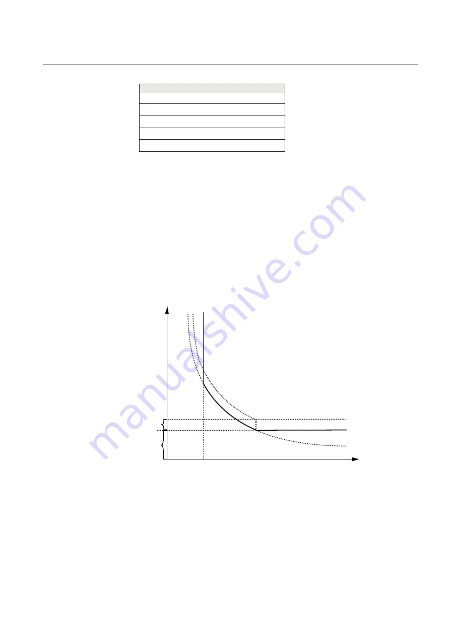
tMin1
: Minimum operate time for all inverse time characteristics. At high currents
the inverse time characteristic might give a very short operation time. By setting
this parameter, the operation time of the step can never be shorter than the setting.
Setting range: 0.000 - 60.000s in steps of 0.001s.
Operate
time
Current
tDef1
tMin1
IMin1
IEC16000212-1-en.vsdx
IEC16000212 V1 EN-US
Figure 51:
Minimum operate current and operate time for inverse time
characteristics
In order to fully comply with the definition of the curve, the setting parameter
tMin1
shall be set to a value equal to the operating time of the selected inverse
curve for twenty times the set current pickup value. Note that the operate time is
dependent on the selected time multiplier setting
k1
.
1MRK 506 375-UEN A
Section 8
Current protection
Railway application RER670 2.2 IEC
165
Application manual
Summary of Contents for RELION RER670
Page 1: ...RELION 670 SERIES Railway application RER670 Version 2 2 IEC Application manual ...
Page 2: ......
Page 22: ...16 ...
Page 48: ...42 ...
Page 70: ...64 ...
Page 80: ...74 ...
Page 100: ...94 ...
Page 210: ...204 ...
Page 364: ...358 ...
Page 384: ...378 ...
Page 468: ...462 ...
Page 494: ...488 ...
Page 504: ...498 ...
Page 505: ...499 ...


