LD
CM
LD
CM
LD
CM
LD
CM
LD
CM
LD
CM
LD
CM
LD
CM
LD
CM
LD
CM
LD
CM
LD
CM
LD
CM
LD
CM
LD
CM
LD
CM
en06000519-2.vsd
IEC06000519 V2 EN-US
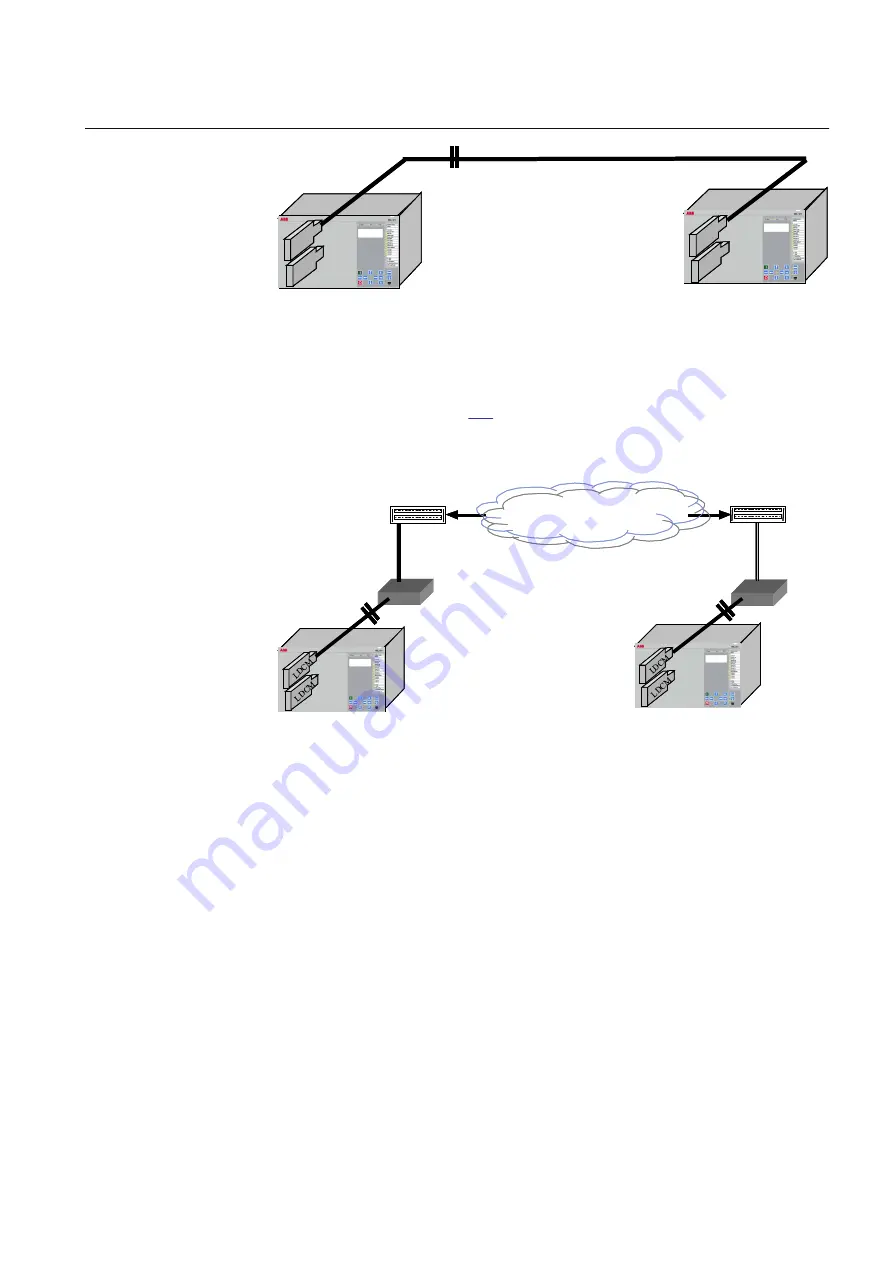
Figure 191:
Direct fibre optical connection between two IEDs with LDCM
The LDCM can also be used together with an external optical to galvanic G.703
converter as shown in figure
. These solutions are aimed for connections to a
multiplexer, which in turn is connected to a telecommunications transmission
network (for example PDH).
Telecom. Network
*)
*)
Multiplexer
Multiplexer
en05000527-2.vsd
*) Converting optical to galvanic G.703
IEC05000527 V2 EN-US
Figure 192:
LDCM with an external optical to galvanic converter and a
multiplexer
When an external modem G.703 is used, the connection between LDCM and the
modem is made with a multimode fibre of max. 3 km length. The IEEE/ANSI
C37.94 protocol is always used between LDCM and the modem.
19.1.3
Setting guidelines
M12454-3 v6
64 kbit and 2 Mbit mode common settings
ChannelMode
defines how an IED discards the LDCM information when one of
the IEDs in the system is out of service: it can either be done on the IED out of
service by setting all local LDCMs to channel mode
OutOfService
or at the remote
1MRK 506 375-UEN A
Section 19
Remote communication
Railway application RER670 2.2 IEC
455
Application manual
Summary of Contents for RELION RER670
Page 1: ...RELION 670 SERIES Railway application RER670 Version 2 2 IEC Application manual ...
Page 2: ......
Page 22: ...16 ...
Page 48: ...42 ...
Page 70: ...64 ...
Page 80: ...74 ...
Page 100: ...94 ...
Page 210: ...204 ...
Page 364: ...358 ...
Page 384: ...378 ...
Page 468: ...462 ...
Page 494: ...488 ...
Page 504: ...498 ...
Page 505: ...499 ...


