1.
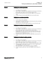
Change the magnitude and angle of phase-to-earth voltage in phase L1 to
achieve impedances at test points P1, P2, …, P8. At the same time, inject
voltage magnitude of 0.0 V and current of 0.0 A in phase L2.
2.
For each test point, observe that the output signals STELEMST and
STNDZL1 are activated.
3.
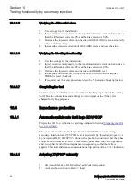
Repeat the above test by injecting phase-to-earth voltage in phase L2 in
accordance with test points and steps described above and observe that the
output signals STELEMST and STNDZL2 are activated.
Change setting parameter
CharStartZ<
to Quadrilateral and set
OpLoadEnch
to
On. Also, Set
X1Start
,
REOverRLStart
,
XEOverXLStart
,
LineAng
,
AngLd
, and
RFPEStart
to default values. Ensure
RLd
value is lower than
RFPEStart
.
Phase-to-earth fault – quadrilateral characteristic
GUID-D8FECD0C-4B31-4A78-8D3C-0A5243516D39 v2
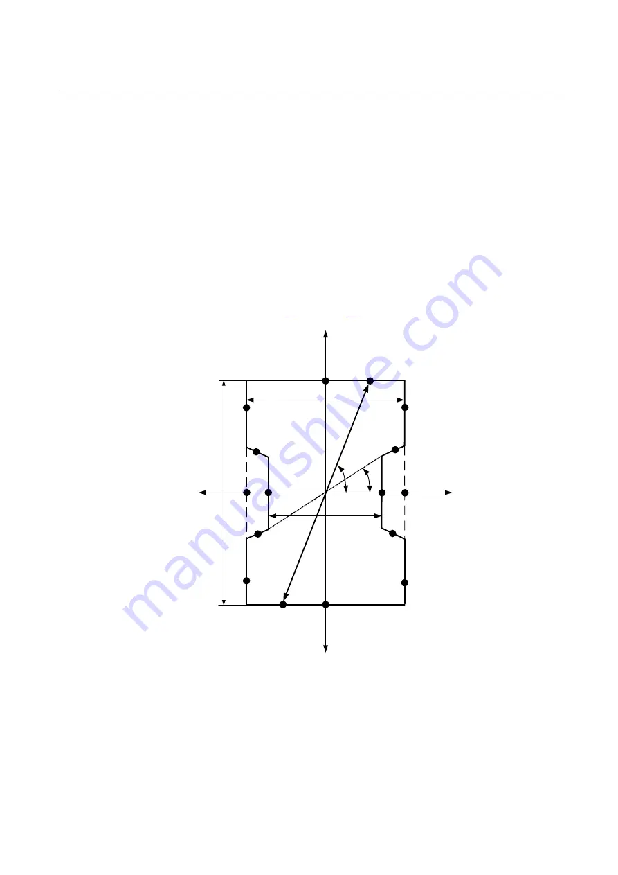
Test points that are to be considered for measurement accuracy of set reactive reach
are shown in Figure
IEC15000434-2-en.vsd
R
jX
RLd
RFPEStart
X1Start
P2
P1
P3
P4
P8
P9
P 10
P 11
P 13
P 14
P 15
P16
P7
P5
P6
ArgLd
( )
( )
P12
LineAng
IEC15000434 V2 EN-US
Figure 18:
Proposed test points for phase-to-earth loop of quadrilateral
characteristic in compensated/high impedance earthed systems
1MRK 506 377-UEN C
Section 10
Testing functionality by secondary injection
Railway application RER670 2.2 IEC
91
Commissioning manual
Summary of Contents for RELION RER670
Page 1: ...RELION 670 SERIES Railway application RER670 Version 2 2 IEC Commissioning manual...
Page 2: ......
Page 26: ...20...
Page 54: ...48...
Page 58: ...52...
Page 62: ...56...
Page 80: ...74...
Page 188: ...182...
Page 194: ...188...
Page 204: ...198...
Page 214: ...208...
Page 215: ...209...

