(
)
1
5.3
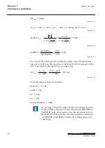
35.7
SB
Z
j
=
+
W
EQUATION1330 V1 EN-US
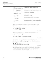
Positive sequence source impedance behind B bus
max
1000
S
MVA
=
EQUATION1331 V1 EN-US
Maximum expected load in direction from A to B (with minimum
system operating voltage U
min
)
(
)
max
cos
0.95
j
=
EQUATION1332 V1 EN-US
Power factor at maximum line loading
max
25
j
=
°
EQUATION1333 V1 EN-US
Maximum expected load angle
2.5
si
f
Hz
=
EQUATION1334 V1 EN-US
Maximum possible initial frequency of power oscillation
7.0
sc
f
Hz
=
EQUATION1335 V1 EN-US
Maximum possible consecutive frequency of power oscillation
The minimum load impedance at minimum expected system voltage is equal to
equation
2
2
min
min
max
380
144.4
1000
L
U
Z
S
=
=
=
W
EQUATION1337 V1 EN-US
(Equation 13)
The minimum load resistance R
Lmin
at maximum load and minimum system
voltage is equal to equation
.
(
)
min
min
max
cos
144.4 0.95 137.2
L
L
R
Z
j
=
×
=
×
=
W
EQUATION1338 V1 EN-US
(Equation 14)
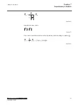
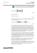
The system impedance Z
S
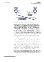
is determined as a sum of all impedances in an
equivalent two-machine system, see figure
. Its value is calculated according to
(
)
1
1
1
17.16
154.8
S
SA
L
SB
Z
Z
Z
Z
j
=
+
+
=
+
W
EQUATION1339 V1 EN-US
(Equation 15)
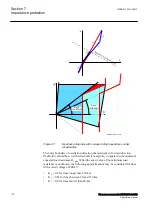
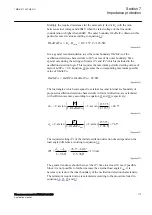
The calculated value of the system impedance is of informative nature and helps in
determining the position of the oscillation center, see figure
general case calculated according to equation
Section 7
1MRK 511 407-UEN C
Impedance protection
110
Phasor measurement unit RES670 2.2 IEC
Application manual
Summary of Contents for Relion RES670
Page 1: ...RELION 670 SERIES Phasor measurement unit RES670 Version 2 2 IEC Application manual...
Page 2: ......
Page 46: ...40...
Page 52: ...46...
Page 92: ...86...
Page 112: ...106...
Page 178: ...172...
Page 216: ...210...
Page 232: ...226...
Page 286: ...280...
Page 328: ...322...
Page 340: ...334...
Page 380: ...374...
Page 381: ...375...

