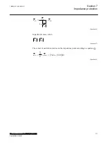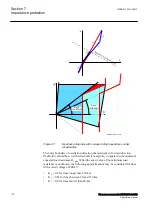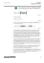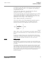
Index PHS designates correspondence to FDPSPDIS or FRPSPDIS
function and index PSD the correspondence to ZMRPSB function.
(
)
tan
arc tan
³
PSD
PHS
ArgLd
ArgLd
kLdRFw
EQUATION1353 V2 EN-US
(Equation 29)
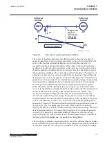
max
25
PSD
ArgLd
j
=
=
°
EQUATION1354 V1 EN-US
(Equation 30)
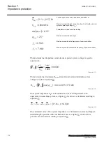
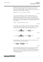
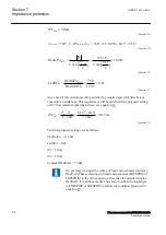
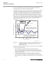
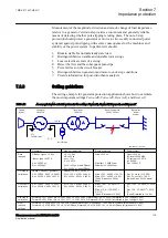
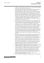
then it is necessary to set the load argument in FDPSPDIS or FRPSPDIS function
to not less than equation
.
(
)
( )
tan
tan 25
arc tan
arc tan
37.5
0.61
é
ù
é
ù
°
³
=
=
°
ê
ú
ê
ú
ë
û
ë
û
PSD
PHS
ArgLd
ArgLd
kLdRFw
EQUATION1355 V1 EN-US
(Equation 31)
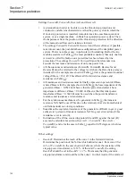
It is recommended to set the corresponding resistive reach parameters in reverse
direction (
RLdOutRv
and
kLdRRv
) to the same values as in forward direction,
unless the system operating conditions, which dictate motoring and generating
types of oscillations, require different values. This decision must be made on basis
of possible system contingency studies especially in cases when the direction of
transmitted power may change fast in short periods of time. It is recommended to
use different setting groups for operating conditions, which are changing only
between different periods of year (summer, winter).
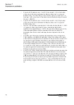
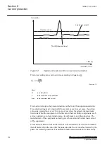
System studies should determine the settings for the hold timer
tH
. The purpose of
this timer is to secure continuous output signal from the Power swing detection
function (ZMRPSB) during the power swing, even after the transient impedance
leaves ZMRPSB operating characteristic and is expected to return within a certain
time due to continuous swinging. Consider the minimum possible speed of power
swinging in a particular system.
The
tR1
inhibit timer delays the influence of the detected residual current on the
inhibit criteria for ZMRPSB. It prevents operation of the function for short
transients in the residual current measured by the IED.
The
tR2
inhibit timer disables the output START signal from ZMRPSB function, if
the measured impedance remains within ZMRPSB operating area for a time longer
than the set
tR2
value. This time delay was usually set to approximately two
seconds in older power-swing devices.
1MRK 511 407-UEN C
Section 7
Impedance protection
Phasor measurement unit RES670 2.2 IEC
115
Application manual
Summary of Contents for Relion RES670
Page 1: ...RELION 670 SERIES Phasor measurement unit RES670 Version 2 2 IEC Application manual...
Page 2: ......
Page 46: ...40...
Page 52: ...46...
Page 92: ...86...
Page 112: ...106...
Page 178: ...172...
Page 216: ...210...
Page 232: ...226...
Page 286: ...280...
Page 328: ...322...
Page 340: ...334...
Page 380: ...374...
Page 381: ...375...

