


Settings
ForwardR
,
ForwardX
,
ReverseR
, and
ReverseX
.
•
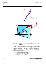
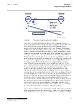
A precondition in order to be able to use the Out-of-step protection and
construct a suitable lens characteristic is that the power system in which the
Out-of-step protection is installed, is modeled as a two-machine equivalent
system, or as a single machine – infinite bus equivalent power system. Then
the impedances from the position of the Out-of-step protection in the direction
of the normal load flow can be taken as forward.
•
The settings
ForwardX
,
ForwardR
,
ReverseX
and
ReverseR
must, if possible,
take into account, the post-disturbance configuration of the simplified power
system. This is not always easy, in particular with islanding. But for the two
machine model as in Table
, the most probable scenario is that only one line
is in service after the fault on one power line has been cleared by line
protections. The settings
ForwardX
,
ForwardR
must therefore take into
account the reactance and resistance of only one power line.
•
All the reactances and resistances (ForwardX, ForwardR, ReverseX and
ReverseR) must be referred to the voltage level where the Out-of-step relay is
installed; for the example case shown in Table
, this is the generator nominal
voltage UBase = 13.8 kV. This affects all the forward reactances and
resistances in Table
.
•
All reactances and resistances must be finally expressed in percent of ZBase,
where ZBase is for the example shown in Table
generator, ZBase = 0.9522 Ω. Observe that the power transformer’s base
impedance is different, ZBase = 0.6348 Ω. Observe that this latter power
transformer ZBase = 0.6348 Ω must be used when the power transformer
reactance and resistance are transformed.
•
For the synchronous machines as the generator in Table
reactance Xd' shall be used. This due to the relatively slow electromechanical
oscillations under out-of-step conditions.
•
Sometimes the equivalent resistance of the generator is difficult to get. A good
estimate is 1 percent of transient reactance Xd'. No great error is done if this
resistance is set to zero (0).
•
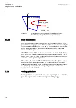
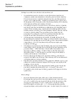
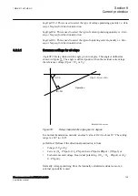
Inclination of the Z-line, connecting points SE and RE, against the real (R)
axis can be calculated as arctan ((
ReverseX
+
ForwardX
) / (
ReverseR
+
ForwardR
)), and is for the case in Table
equal to 84.55 degrees, which is a
typical value.
Other settings:
•
ReachZ1
: Determines the reach of the zone 1 in the forward direction.
Determines the position of the X-line which delimits zone 1 from zone 2. Set
in % of
ForwardX
. In the case shown in Table
step-up power transformer is 11.32 % of the total
ForwardX
, the setting
ReachZ1
should be set to
ReachZ1
=
12
%. This means that the generator –
step-up transformer unit would be in the zone 1. In other words, if the centre of
Section 7
1MRK 511 407-UEN C
Impedance protection
120
Phasor measurement unit RES670 2.2 IEC
Application manual
Summary of Contents for Relion RES670
Page 1: ...RELION 670 SERIES Phasor measurement unit RES670 Version 2 2 IEC Application manual...
Page 2: ......
Page 46: ...40...
Page 52: ...46...
Page 92: ...86...
Page 112: ...106...
Page 178: ...172...
Page 216: ...210...
Page 232: ...226...
Page 286: ...280...
Page 328: ...322...
Page 340: ...334...
Page 380: ...374...
Page 381: ...375...