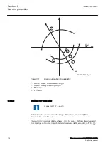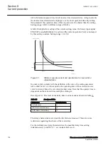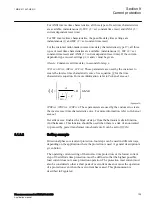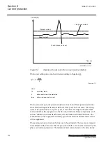
•
OperationZ1
: Operation zone 1
On
,
Off
. If
OperationZ1
=
Off
, all pole-slips
with centre of the electromechanical oscillation within zone 1 are ignored.
Default setting =
On
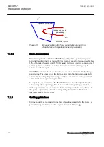
. More likely to be used is the option to extend zone 1 so
that zone 1 even covers zone 2. This feature is activated by the input to extend
the zone 1 (EXTZ1).
•
OperationZ2
: Operation zone 2
On
,
Off
. If
OperationZ1
=
Off
, all pole-slips
with centre of the electromechanical oscillation within zone 2 are ignored.
Default setting =
On
.
•
tBreaker
: Circuit breaker opening time. Use the default value
tBreaker
=
0.000
s
if unknown. If the value is known, then a value higher than 0.000 is
specified, for example
tBreaker
=
0.040 s
: the out-of-step function gives a trip
command approximately 0.040 seconds before the currents reach their
minimum value. This in order to decrease the stress imposed to the circuit
breaker.
•
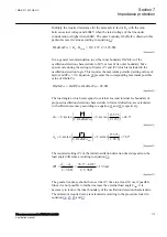
GlobalBaseSel
: This setting identifies the Global Base Values Group where
UBase
and
IBase
are defined. In particular:
UBase
is the voltage at the point
where the Out-of-step protection is connected. If the protection is connected to
the generator output terminals, then
UBase
is the nominal (rated) phase to
phase voltage of the protected generator. All the resistances and reactances are
measured and displayed referred to voltage
Ubase
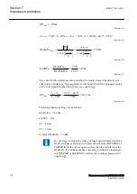
. Observe that
ReverseX
,
ForwardX
,
ReverseR
, and
ForwardR
must be given referred to
UBase.IBase
is
the protected generator nominal (rated) current, if the Out-of-step protection
belongs to a generator protection scheme.
•
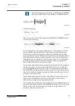
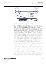
InvertCTCurr
: If the currents fed to the Out-of-step protection are measured on
the protected generator neutral side (LV-side) then inversion is not necessary
(
InvertCTCurr
=
Off
), provided that the CT’s star point earthing complies with
ABB recommendations, as it is shown in Table
Out-of-step protection are measured on the protected generator terminals side,
then invertion is necessary (
InvertCTCurr
=
On
), provided that the CT’s star
point earthing complies with ABB recommendations, as it is shown in Table
.
Section 7
1MRK 511 407-UEN C
Impedance protection
122
Phasor measurement unit RES670 2.2 IEC
Application manual
Summary of Contents for Relion RES670
Page 1: ...RELION 670 SERIES Phasor measurement unit RES670 Version 2 2 IEC Application manual...
Page 2: ......
Page 46: ...40...
Page 52: ...46...
Page 92: ...86...
Page 112: ...106...
Page 178: ...172...
Page 216: ...210...
Page 232: ...226...
Page 286: ...280...
Page 328: ...322...
Page 340: ...334...
Page 380: ...374...
Page 381: ...375...

