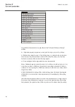
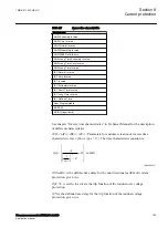

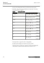


Table 17:
Inverse time characteristics
Curve name
ANSI Extremely Inverse
ANSI Very Inverse
ANSI Normal Inverse
ANSI Moderately Inverse
ANSI/IEEE Definite time
ANSI Long Time Extremely Inverse
ANSI Long Time Very Inverse
ANSI Long Time Inverse
IEC Normal Inverse
IEC Very Inverse
IEC Inverse
IEC Extremely Inverse
IEC Short Time Inverse
IEC Long Time Inverse
IEC Definite Time
User Programmable
ASEA RI
RXIDG (logarithmic)
See chapter “Inverse time characteristics” in Technical Manual for the description
of different characteristics
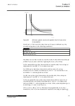
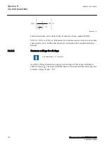
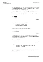
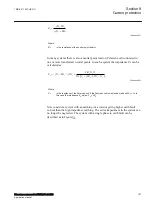
tPCrv, tACrv, tBCrv, tCCrv
: Parameters for customer creation of inverse time
characteristic curve (Curve type = 17). The time characteristic equation is:
[ ]
=
+
×
-
>
æ
ö
ç
÷
ç
÷
ç
÷
æ
ö
ç
÷
ç
÷
è
ø
è
ø
p
A
t s
B
InMult
i
C
in
EQUATION1958 V1 EN-US
(Equation 54)
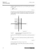
tINNonDir
is the definite time delay for the non directional earth fault current
protection, given in s.
OpUN>
is set
On
to activate the trip function of the residual over voltage
protection.
tUN
is the definite time delay for the trip function of the residual voltage
protection, given in s.
1MRK 511 407-UEN C
Section 8
Current protection
Phasor measurement unit RES670 2.2 IEC
157
Application manual
Summary of Contents for Relion RES670
Page 1: ...RELION 670 SERIES Phasor measurement unit RES670 Version 2 2 IEC Application manual...
Page 2: ......
Page 46: ...40...
Page 52: ...46...
Page 92: ...86...
Page 112: ...106...
Page 178: ...172...
Page 216: ...210...
Page 232: ...226...
Page 286: ...280...
Page 328: ...322...
Page 340: ...334...
Page 380: ...374...
Page 381: ...375...


