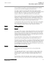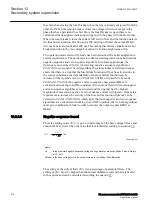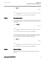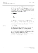
Current circuit supervision CCSSPVC compares the residual current from a three-
phase set of current transformer cores with the neutral point current on a separate
input taken from another set of cores on the same current transformer.
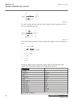
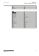
IMinOp
: It must be set as a minimum to twice the residual current in the supervised
CT circuits under normal service conditions and rated primary current.
Ip>Block
: It is normally set at
150%
to block the function during transient
conditions.
The FAIL output is connected to the blocking input of the protection function to be
blocked at faulty CT secondary circuits.
13.2
Fuse failure supervision FUFSPVC
IP14556-1 v3
13.2.1
Identification
M14869-1 v4
Function description
IEC 61850
identification
IEC 60617
identification
ANSI/IEEE C37.2
device number
Fuse failure supervision
FUFSPVC
-
-
13.2.2
Application
SEMOD113803-4 v10
Different protection functions within the protection IED, operates on the basis of
the measured voltage in the relay point. Examples are:
•
impedance protection functions
•
undervoltage function
•
energizing check function and voltage check for the weak infeed logic
These functions can operate unintentionally if a fault occurs in the secondary
circuits between the voltage instrument transformers and the IED.
It is possible to use different measures to prevent such unwanted operations.
Miniature circuit breakers in the voltage measuring circuits should be located as
close as possible to the voltage instrument transformers, and shall be equipped with
auxiliary contacts that are wired to the IEDs. Separate fuse-failure monitoring IEDs
or elements within the protection and monitoring devices are another possibilities.
These solutions are combined to get the best possible effect in the fuse failure
supervision function (FUFSPVC).
FUFSPVC function built into the IED products can operate on the basis of external
binary signals from the miniature circuit breaker or from the line disconnector. The
Section 13
1MRK 511 407-UEN C
Secondary system supervision
212
Phasor measurement unit RES670 2.2 IEC
Application manual
Summary of Contents for Relion RES670
Page 1: ...RELION 670 SERIES Phasor measurement unit RES670 Version 2 2 IEC Application manual...
Page 2: ......
Page 46: ...40...
Page 52: ...46...
Page 92: ...86...
Page 112: ...106...
Page 178: ...172...
Page 216: ...210...
Page 232: ...226...
Page 286: ...280...
Page 328: ...322...
Page 340: ...334...
Page 380: ...374...
Page 381: ...375...


