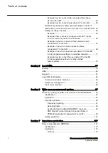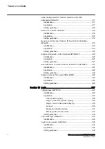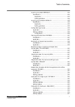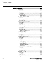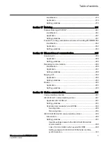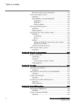
Example how to connect delta connected three-phase
CT set to the IED....................................................................60
Example how to connect single-phase CT to the IED............ 63
Relationships between setting parameter Base Current, CT
Example................................................................................. 65
Examples how to connect, configure and set VT inputs
for most commonly used VT connections.............................. 66
Examples on how to connect a three phase-to-earth
connected VT to the IED........................................................ 67
Example on how to connect a phase-to-phase
connected VT to the IED........................................................ 69
Example on how to connect an open delta VT to the IED
for high impedance earthed or unearthed networks...............71
Example how to connect the open delta VT to the IED
for low impedance earthed or solidly earthed
power systems....................................................................... 74
Section 5 Local HMI....................................................................... 77
Display..............................................................................................78
LEDs.................................................................................................80
Keypad............................................................................................. 81
Local HMI functionality..................................................................... 83
Protection and alarm indication................................................... 83
Parameter management .............................................................84
Front communication...................................................................85
Section 6 Wide area measurement system....................................87
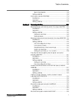
Protocol reporting via IEEE 1344 and C37.118 PMUREPORT........87
Identification................................................................................ 87
Application...................................................................................87
Operation principle...................................................................... 89
Frequency reporting............................................................... 91
Reporting filters...................................................................... 93
Scaling Factors for ANALOGREPORT channels................... 94
PMU Report Function Blocks Connection Rules in
PCM600 Application Configuration Tool (ACT)......................95
Setting guidelines...................................................................... 101
Section 7 Impedance protection...................................................107
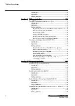
Power swing detection ZMRPSB ...................................................107
General.................................................................................107
Table of contents
2
Phasor measurement unit RES670 2.2 IEC
Application manual
Summary of Contents for Relion RES670
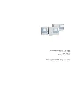
Page 1: ...RELION 670 SERIES Phasor measurement unit RES670 Version 2 2 IEC Application manual...
Page 2: ......
Page 46: ...40...
Page 52: ...46...
Page 92: ...86...
Page 112: ...106...
Page 178: ...172...
Page 216: ...210...
Page 232: ...226...
Page 286: ...280...
Page 328: ...322...
Page 340: ...334...
Page 380: ...374...
Page 381: ...375...


