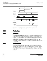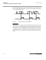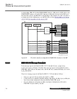
IEC01000240_2_en.vsd
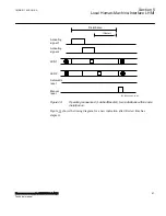
Activating
signal 2
LED 2
Manual
reset
Activating
signal 1
Automatic
reset
LED 1
Disturbance
tRestart
Disturbance
tRestart
IEC01000240 V2 EN-US
Figure 24:
Operating sequence 6 (LatchedReset-S), two different disturbances
shows the timing diagram when a new indication appears after the first one
has reset but before
tRestart
has elapsed.
Section 5
1MRK 511 408-UUS A
Local Human-Machine-Interface LHMI
98
Phasor measurement unit RES670 2.2 ANSI
Technical manual
Summary of Contents for Relion RES670
Page 1: ...RELION 670 SERIES Phasor measurement unit RES670 Version 2 2 ANSI Technical manual ...
Page 2: ......
Page 276: ...270 ...
Page 306: ...300 ...
Page 360: ...354 ...
Page 406: ...400 ...
Page 614: ...608 ...
Page 732: ...726 ...
Page 748: ...742 ...
Page 884: ...878 ...
Page 932: ...926 ...
Page 933: ...927 ...


