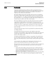
In addition, there is also a separate non-directional residual over voltage protection,
with its own definite time delay
tVN
and set level
VN_PU
.
For trip, the residual voltage 3V
0
shall be larger than the set level (
VN_PU
).
Trip from this function can be blocked from the binary input BLKVN.
When the function picks up, binary output signal PUVN is activated. If the output
signal PUVN is active for the set delay
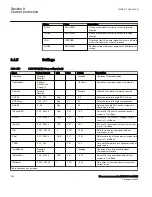
tVNNonDir
, the binary output signals TRIP and
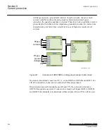
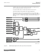
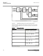
TRUN get activated. A simplified logical diagram of the total function is shown in
Figure
.
en06000653_ansi.vsd
INNonDirPU
UN_PU
OpMODE=INcosPhi
Pickup_N
INCosPhiPU
OpMODE=INVNCosPhi
INVNCosPhiPU
Phi in RCA +- ROA
OpMODE=IN and Phi
DirMode = Forw
Forw
DirMode = Rev
Rev
PUNDIN
TRNDIN
PUVN
TRVN
AND
AND
AND
OR
AND
AND
AND
OR
PUDIRIN
PUFW
PUREV
0 - t
0 - t
0
0
TimeChar = DefTime
TRDIRIN
AND
SN
t
TimeChar = InvTime
AND
ANSI06000653 V1 EN-US
Figure 76:
Simplified logical diagram of the sensitive ground fault current protection
1MRK 511 408-UUS A
Section 8
Current protection
Phasor measurement unit RES670 2.2 ANSI
241
Technical manual
Summary of Contents for Relion RES670
Page 1: ...RELION 670 SERIES Phasor measurement unit RES670 Version 2 2 ANSI Technical manual ...
Page 2: ......
Page 276: ...270 ...
Page 306: ...300 ...
Page 360: ...354 ...
Page 406: ...400 ...
Page 614: ...608 ...
Page 732: ...726 ...
Page 748: ...742 ...
Page 884: ...878 ...
Page 932: ...926 ...
Page 933: ...927 ...


