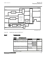
ANSI05000016-2-en.vsd
Voltage
IDMT Voltage
Time
VA
VB
VC
ANSI05000016 V2 EN-US
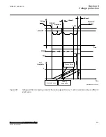
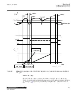
Figure 97:
Voltage used for the inverse time characteristic integration
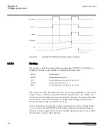
Operation of the trip signal requires that the overvoltage condition continues for at
least the user set time delay. This time delay is set by the parameter
t1
and
t2
for
definite time mode (DT) and by selected voltage level dependent time curves for the
inverse time mode (TOV). If the PICKUP condition, with respect to the measured
voltage ceases during the delay time, and is not fulfilled again within a user defined
reset time (
tReset1
and
tReset2
for the definite time and
tIReset1
and
tIReset2
for the
inverse time) the corresponding PICKUP output is reset, after that the defined reset
time has elapsed. Here it should be noted that after leaving the hysteresis area, the
PICKUP condition must be fulfilled again and it is not sufficient for the signal to only
return back to the hysteresis area. The hysteresis value for each step is settable
HystAbsn
(where
n
means either 1 or 2 respectively) to allow a high and accurate reset
of the function. For OV2PTOV (59) the TOV reset time is constant and does not
depend on the voltage fluctuations during the drop-off period. However, there are three
ways to reset the timer: either the timer is reset instantaneously, or the timer value is
frozen during the reset time, or the timer value is linearly decreased during the reset
time.
1MRK 511 408-UUS A
Section 9
Voltage protection
Phasor measurement unit RES670 2.2 ANSI
293
Technical manual
Summary of Contents for Relion RES670
Page 1: ...RELION 670 SERIES Phasor measurement unit RES670 Version 2 2 ANSI Technical manual ...
Page 2: ......
Page 276: ...270 ...
Page 306: ...300 ...
Page 360: ...354 ...
Page 406: ...400 ...
Page 614: ...608 ...
Page 732: ...726 ...
Page 748: ...742 ...
Page 884: ...878 ...
Page 932: ...926 ...
Page 933: ...927 ...

