[ ]
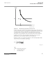
2
1
r
t
t s
td
i
pickupn
=
×
-
æ
ö
ç
÷
ç
÷
ç
÷
æ
ö
ç ç
÷
÷
è è
ø
ø
ANSIEQUATION1197 V1 EN-US
(Equation 94)
where:
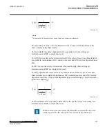
The set value t
r
is the reset time in case of zero current after fault clearance.
The possibility of choice of reset characteristics is to some extent dependent of the
choice of time delay characteristic.
For the definite time delay characteristics the possible reset time settings are
instantaneous and IEC constant time reset.
For ANSI inverse time delay characteristics all three types of reset time characteristics
are available; instantaneous, IEC constant time reset and ANSI current dependent reset
time.
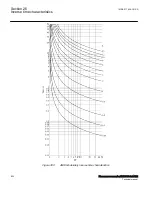
For IEC inverse time delay characteristics the possible delay time settings are
instantaneous and IEC set constant time reset).
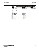
For the programmable inverse time delay characteristics all three types of reset time
characteristics are available; instantaneous, IEC constant time reset and ANSI current
dependent reset time. If the current dependent type is used settings pr, tr and cr must be
given, see equation
[ ]
r
pr
t
t s
td
i
cr
pickupn
=
×
-
æ
ö
ç
÷
ç
÷
ç
÷
æ
ö
ç ç
÷
÷
è è
ø
ø
ANSIEQUATION1198 V1 EN-US
(Equation 95)
For RI and RD inverse time delay characteristics the possible delay time settings are
instantaneous and IEC constant time reset.
GUID-F7AA2194-4D1C-4475-8853-C7D064912614 v4
When inverse time overcurrent characteristic is selected, the trip time
of the stage will be the sum of the inverse time delay and the set
1MRK 511 408-UUS A
Section 26
Inverse time characteristics
Phasor measurement unit RES670 2.2 ANSI
887
Technical manual
Summary of Contents for Relion RES670
Page 1: ...RELION 670 SERIES Phasor measurement unit RES670 Version 2 2 ANSI Technical manual ...
Page 2: ......
Page 276: ...270 ...
Page 306: ...300 ...
Page 360: ...354 ...
Page 406: ...400 ...
Page 614: ...608 ...
Page 732: ...726 ...
Page 748: ...742 ...
Page 884: ...878 ...
Page 932: ...926 ...
Page 933: ...927 ...


