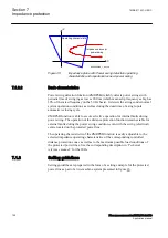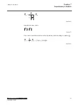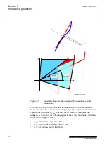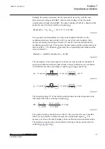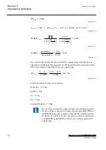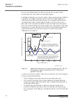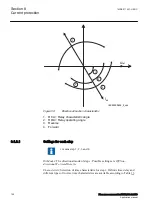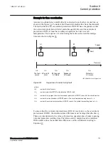
Measurement of the magnitude, direction and rate-of-change of load impedance
relative to a generator’s terminals provides a convenient and generally reliable
means of detecting whether pole-slipping is taking place. The out-of-step
protection should protect a generator or motor (or two weakly connected power
systems) against pole-slipping with severe consequences for the machines and
stability of the power system. In particular it should:
1. Remain stable for normal steady state load.
2. Distinguish between stable and unstable rotor swings.
3. Locate electrical centre of a swing.
4. Detect the first and the subsequent pole-slips.
5. Prevent stress on the circuit breaker.
6. Distinguish between generator and motor out-of-step conditions.
7. Provide information for post-disturbance analysis.
7.2.3
Setting guidelines
GUID-CB86FCF6-8718-40BE-BDF2-028C24AB367D v6
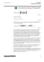
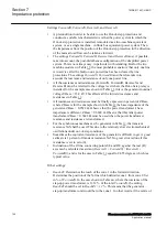
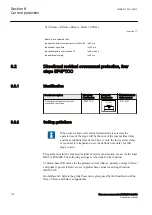
The setting example for generator protection application shows how to calculate
the most important settings
ForwardR
,
ForwardX
,
ReverseR
, and
ReverseX
.
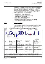
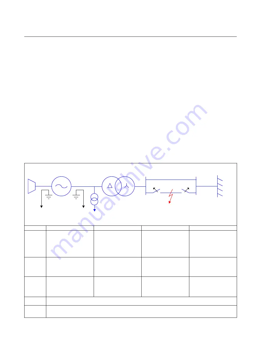
Table 12:
An example how to calculate values for the settings ForwardR, ForwardX, ReverseR, and ReverseX
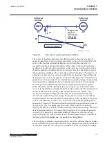
Turbine
(hydro)
Generator
200 MVA
Transformer
300 MVA
Double power line
230 kV, 300 km
Equivalent
power
system
CT 1
To OOS relay
CT 2
13.8 kV
IEC10000117-2-en.vsd
to OOS relay
IEC10000117 V2 EN-US
Generator
Step-up transformer
Single power line
Power system
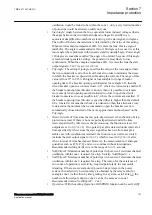
Data
required
UBase = Ugen = 13.8 kV
IBase = Igen = 8367 A
Xd' = 0.2960 pu
Rs = 0.0029 pu
U1 = 13.8 kV
U2 = 230 kV
usc = 10%
I1 = 12 551 A
Xt = 0.1000 pu (transf. ZBase)
Rt = 0.0054 pu (transf. ZBase)
Uline = 230 kV
Xline/km = 0.4289 Ω/km
Rline/km = 0.0659 Ω/km
Unom = 230 kV
SC level = 5000 MVA
SC current = 12 551 A
φ = 84.289°
Ze = 10.5801 Ω
1-st step in
calculation
ZBase = 0.9522 Ω (generator)
Xd' = 0.2960 · 0.952 = 0.282 Ω
Rs = 0.0029 · 0.952 = 0.003 Ω
ZBase (13.8 kV) = 0.6348 Ω
Xt = 0.100 · 0.6348 = 0.064 Ω
Rt = 0.0054 · 0.635 = 0.003 Ω
Xline = 300 · 0.4289 = 128.7 Ω
Rline = 300 · 0.0659 = 19.8 Ω
(X and R above on 230 kV
basis)
Xe = Z
e
· sin (φ) = 10.52 Ω
Re = Z
e
· cos (φ) = 1.05 Ω
(Xe and Re on 230 kV basis)
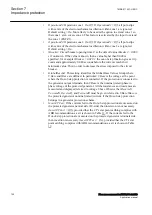
2-nd step in
calculation
Xd' = 0.2960 · 0.952 = 0.282 Ω
Rs = 0.0029 · 0.952 = 0.003 Ω
Xt = 0.100 · 0.6348 = 0.064 Ω
Rt = 0.0054 · 0.635 = 0.003 Ω
Xline= 128.7 · (13.8/230)
2
=
0.463 Ω
Rline = 19.8 · (13.8/230)
2
=
0.071 Ω
(X and R referred to 13.8 kV)
Xe = 10.52 · (13.8/230)
2
= 0.038
Ω
Re = 1.05 · (13.8/230)
2
= 0.004
Ω
(X and R referred to 13.8 kV)
3-rd step in
calculation
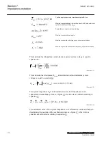
ForwardX = Xt + Xline + Xe = 0.064 + 0.463 + 0.038 = 0.565 Ω; ReverseX = Xd' = 0.282 Ω (all referred to gen. voltage 13.8 kV)
ForwardR = Rt + Rline + Re = 0.003 + 0.071 + 0.004 = 0.078 Ω; ReverseR = Rs = 0.003 Ω (all referred to gen. voltage 13.8 kV)
Final
resulted
settings
ForwardX = 0.565/0.9522 · 100 = 59.33 in % ZBase; ReverseX = 0.282/0.9522 · 100 = 29.6 in % ZBase (all referred to 13.8 kV)
ForwardR = 0.078/0.9522 · 100 = 8.19 in % ZBase; ReverseR = 0.003/0.9522 · 100 = 0.29 in % ZBase (all referred to 13.8 kV)
1MRK 511 407-UEN C
Section 7
Impedance protection
Phasor measurement unit RES670 2.2 IEC
119
Application manual
Summary of Contents for Relion RES670
Page 1: ...RELION 670 SERIES Phasor measurement unit RES670 Version 2 2 IEC Application manual...
Page 2: ......
Page 46: ...40...
Page 52: ...46...
Page 92: ...86...
Page 112: ...106...
Page 178: ...172...
Page 216: ...210...
Page 232: ...226...
Page 286: ...280...
Page 328: ...322...
Page 340: ...334...
Page 380: ...374...
Page 381: ...375...

