background image

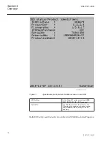
The output data generated from the pulse counter function include data about the
status of the counter and counter values.

6.6.2 

Function for energy calculation and demand handling

ETPMMTR

Main menu/Measurements/Metering/ThreePhEnergMeas(MMTR)/
ETPMMTR:x

The output data generated from the energy measuring function includes active
forward/reverse energy and reactive forward/reverse energy.

Section 6

1MRK511251-UEN B

Read measured values

30

Operator's manual

Summary of Contents for Relion RES670

Page 1: ...Relion 670 series Phasor measurement unit RES670 Operator s manual...

Page 2: ......

Page 3: ...Document ID 1MRK511251 UEN Issued February 2015 Revision B Product version 1 2 Copyright 2012 ABB All rights reserved...

Page 4: ...or disclosed only in accordance with the terms of such license Trademarks ABB and Relion are registered trademarks of the ABB Group All other brand or product names mentioned in this document may be...

Page 5: ...roduct failure would create a risk for harm to property or persons including but not limited to personal injuries or death shall be the sole responsibility of the person or entity applying the equipme...

Page 6: ...rning electrical equipment for use within specified voltage limits Low voltage directive 2006 95 EC This conformity is the result of tests conducted by ABB in accordance with the product standards EN...

Page 7: ...tify the IED 15 Section 4 Understand the IED local human machine interface 19 Overview 19 Keypad 19 Key activated screens 21 The Help screen 21 The Reset screen 21 LCD 21 Medium 21 LED 22 Introduction...

Page 8: ...ts 31 Overview 31 Section 8 Handle disturbances 33 Identify a disturbance 33 View disturbance record details 33 View general information 33 View disturbance indications 33 View event recordings 33 Vie...

Page 9: ...s VMSQI 43 Disturbance report DRPRDRE 43 Fault locator LMBRFLO 44 Generic measured value MVGGIO 44 Event function 44 Logical signal status report BINSTATREP 44 Metering 44 Overview 44 Pulse counter lo...

Page 10: ...use failure supervision SDDRFUF 48 Monitoring 48 Overview 48 Event counter CNTGGIO 49 Fault locator LMBRFLO 49 Logic 49 Overview 49 Tripping logic SMPPTRC 49 Trip matrix logic TMAGGIO 49 LogicGate 49...

Page 11: ...tep undervoltage protection UV2PTUV 58 Frequency protection 58 Overfrequency protection SAPTOF 58 Rate of change frequency protection SAPFRC 58 Underfrequency protection SAPTUF 58 Multipurpose protect...

Page 12: ...67 Overview 67 Read measured values and check apparatus status 67 Locating and using the single line diagram 67 Control screen messages 69 Section 13 Reset 71 Reset guide for IED 71 Reset counters 71...

Page 13: ...Section 15 Glossary 79 Table of contents 7 Operator s manual...

Page 14: ...8...

Page 15: ...eringmanual Commissioning manual manual Technical reference IEC09000744 V1 EN The Application Manual AM contains application descriptions setting guidelines and setting parameters sorted per function...

Page 16: ...recommends a sequence for engineering of protection and control functions LHMI functions as well as communication engineering for IEC 61850 and DNP3 1 1 2 About the operator s manual Use the operator...

Page 17: ...s kind of equipment 1 1 4 Related documents Documents related to RES670 Identity number Operator s manual 1MRK 511 251 UEN Installation and commissioning manual 1MRK 511 252 UEN Technical reference ma...

Page 18: ...vision notes Revision Description First issue for 670 series version 1 2 A Maintenance updates PR corrections B Maintenance updates PR corrections Section 1 1MRK511251 UEN B Introduction 12 Operator s...

Page 19: ...site configuration Operating the IED without proper earthing may damage both IED and measuring circuitry and may cause injuries in the event of an accident Never remove any screw from a powered IED or...

Page 20: ...14...

Page 21: ...eference For example the fault currents and voltages at the time of the fault can be documented The operator can also retrieve data about protected objects providing further information for fault anal...

Page 22: ...ries product type REB REC RED REG REL RET and so on ProductDef specifies the version of the product in the following order major version minor version major revision minor revision 1 2 2 0 for example...

Page 23: ...IEDMainFunType Specifies the main IED functionality in accordance to IEC60870 5 103 numbering REL 128 compatible range REC 242 private range RED 192 compatible range RET 176 compatible range REB 207 p...

Page 24: ...18...

Page 25: ...he human machine interface is used to monitor and to some extent control the way the IED operates The configuration designer can add functions that alert to events requiring the attention of the opera...

Page 26: ...00104 V1 EN Press to clear entries cancel commands or edit IEC05000105 V1 EN Press to open the main menu and to move to the default screen IEC05000106 V1 EN Press to set the IED in local or remote con...

Page 27: ...and close ON breakers and disconnectors when using the Single Line Diagram SLD in direct control situations 4 3 2 The Reset screen The reset screen is activated by the Reset key on the front panel of...

Page 28: ...riggered Flashing Terminal in test mode Red Steady Trip command issued 4 5 3 Indication LEDs The LED indication module comprising 15 LEDs is standard in 670 series Its main purpose is to present an im...

Page 29: ...MI Screen 4 7 How to navigate 4 7 1 Read To read values and access information about the objects being monitored the operator must navigate the menu tree using the arrow keys The active submenu or val...

Page 30: ...row keys to change the digit or letter concerned 5 Press the E key once the desired changes have been made 6 Press the left arrow key to move up a level in the HMI tree 7 You will be prompted to confi...

Page 31: ...Report Settings Diagnostics Test and Reset These branch out into a typical tree structure 5 1 Overview The local HMI has the following main menu Control Measurements Events Disturbance records Settin...

Page 32: ...26...

Page 33: ...side of the current transformers CTs 2 Analog secondary values are the quantities measured on the secondary side of the current and voltage transformers These are the quantities measured on the Trans...

Page 34: ...shown here 6 4 1 1 mA input module MIM Main menu Measurements Analog mean values mA modules MIM x Displays input data from the milli ampere module which has six inputs Each input has a range of 20 mA...

Page 35: ...urrent values for a three phase line both magnitude and phase angle for each component are displayed These indicate how well balanced a system is In an ideal balanced system the zero sequence current...

Page 36: ...Function for energy calculation and demand handling ETPMMTR Main menu Measurements Metering ThreePhEnergMeas MMTR ETPMMTR x The output data generated from the energy measuring function includes active...

Page 37: ...ew events 7 1 1 Overview Events displays recorded events such as trips and breaker opened or closed Main menu Events Displays a list of events in chronological order and where each event has a time st...

Page 38: ...32...

Page 39: ...escribed in the sections that follow 8 2 View disturbance record details 8 2 1 View general information By choosing General information after selecting a disturbance record in the list of disturbance...

Page 40: ...splayed The path in the HMI is shown below Main menu Disturbance records Record xx Trip Values 8 3 Trigger a disturbance report manually Using the manual trigger generates an instant disturbance repor...

Page 41: ...ust not be turned off Do not perform a setting change at the same time as a hardware reconfiguration Doing so might cause the IED to malfunction 9 1 System time and synchronization 9 1 1 System time M...

Page 42: ...aylight Savings Time is set here 9 1 2 6 SYNCHIRIG B Main menu Settings Time Synchronization SYNCHIRIG B x The type of input time domain type of encoding and time zone for IRIG B are set here 9 1 2 7...

Page 43: ...ettings Power system Primary values Displays the system frequency 9 2 2 Communication 9 2 2 1 Overview The parameter settings for communications are found under General Settings Communications Communi...

Page 44: ...operation The mode of operation is either steady or pulsed Configuration parameters for IEEE1344 and C37 118 protocol PMUCONF Main Menu Settings General settings Communication Station communication P...

Page 45: ...rimary and secondary values from the measuring transformers The channel type and ratings are shown but cannot be changed The settings for binary inputs and outputs even include the milliampere input m...

Page 46: ...reen Functions Reference channel service values and the Change lock function In the LED submenu there are settings for operation illumination times and sequence types for the LEDs on the IED front pan...

Page 47: ...of the bay control function QCBAY with a setting that gives the local operator priority over the remote operator or vice versa Local Remote switch LocalRemote LocRemControl Main menu Settings General...

Page 48: ...and the Measured value expander block 9 2 6 2 Service values CVMMXN Main menu Settings General Settings Monitoring ServiceValues MMXN CVMMXN x Displays available instances of CVMMXN 9 2 6 3 Current p...

Page 49: ...oltage sequence components VMSQI Main menu Settings General settings Monitoring VoltageSequenceComponents MSQI VMSQI x The voltage sequence components are where the user sets the limits and deadband s...

Page 50: ...unction block and to set the threshold values This is a generic function and therefore the input values depend on the application 9 2 6 10 Event function Main menu Settings General settings Monitoring...

Page 51: ...for accumulated energy values are found here 9 3 Setting group N 9 3 1 Overview There are some default setting groups Under general settings parameters in these groups can be changed to suit the needs...

Page 52: ...n SensDirResOvCurr PSDE 67N SDEPSDE x Includes voltage current operation mode and timer settings 9 3 3 Voltage protection 9 3 3 1 Overview For Voltage protection there are settings for Under voltage O...

Page 53: ...the Operation setting must be On 9 3 4 3 Rate of change frequency protection SAPFRC Main menu Settings Setting Group N Frequency protection RateOfChangeOfFrequency PFRC 81 SAPFRC x Displays available...

Page 54: ...ated current and operation There are six instances of Fuse failure supervision parameters for setting rated current voltage operation mode and several other parameters 9 3 6 2 Current circuit supervis...

Page 55: ...3 8 Logic 9 3 8 1 Overview Under Logic there are settings for Trip logic Trip matrix Logic gate Logic SR memory and Logic timer set Under each of these function categories there are a number of instan...

Page 56: ...Main menu Settings Setting group N Logic LogicSRMemory SRMEMORY x Displays setting parameters for operating mode of memory function 9 3 8 7 LogicTimerSet Main menu Settings Setting Group N Logic Logi...

Page 57: ...e status of each item on the list To identify the type of IED you are confronted with navigate to identifiers using the keypad The path to identity parameters is shown below Main menu Diagnostics IED...

Page 58: ...Communication Rear OEM port CD Displays various communication status signals for rear CD port communication Main menu Diagnostics Communication Redundant PRP Displays communication status for redunda...

Page 59: ...easurement 3 Current protection displays a choice of functions To view data related to these functions it is necessary to choose one from the list and navigate to the screen for the function in questi...

Page 60: ...formed without endangering system stability and a setting with which events can be enabled or disabled 11 3 View binary input values 11 3 1 Overview Binary input values display the state of each indiv...

Page 61: ...ignal matrix for binary outputs SMBO Main menu Test Binary output values SMT binary outputs Displays available sets of binary output values Each set or instance of binary outputs displays the status o...

Page 62: ...lure supervision 11 5 7 Control Main menu Test Function test modes Control Test of synchrocheck and energizing check function 11 5 8 Monitoring Main menu Test Function test modes Monitoring Test of mo...

Page 63: ...Displays available instances of EF4PTOC with a number of measurements per instance The measurements indicate trip and start signal status as well as the 2nd harmonic block signal status 11 6 1 4 Sens...

Page 64: ...2 Rate of change frequency protection SAPFRC Main menu Test Function status Frequency protection RateOfChangeOfFrequency PFRC SAPFRC x Displays available instances of SAPFRC with measurement data for...

Page 65: ...gether with various start and current data 11 6 5 1 Current circuit supervision CCSRDIF Main menu Test Function status Secondary system supervision CurrentCircuitSupervision RDIF 87 CCSRDIF x Displays...

Page 66: ...position of each switch is indicated here There are up to a number of possible switch positions The number of switches and switch positions is determined by the configuration in the PCM configuration...

Page 67: ...tory The maximum number of incoming analog channels is 40 and their Trig status is indicated here The Fault number parameter generates an integer indicating the number of faults recorded since the las...

Page 68: ...asValExpander RANGE_XP x Displays available instances of the function block RANGE_XP These show the boolean values assigned to the integer values generated by analog inputs 11 6 7 10 IEC61850 generic...

Page 69: ...nstances of the function TMAGGIO with some boolean output values per instance The output signals from this function block are typically connected to other logic blocks or directly to IED output contac...

Page 70: ...Station communication MultipleCommandReceive MULTICMDRCV x The MultiCommand Receive indications displayed here show available sets of output data Each set of output data has a number of signals Other...

Page 71: ...vated by a binary input and the SETTING parameter indicates whether or not test mode has been activated by a setting The output data is binary 0 or 1 11 6 12 Authorization Main menu Test Function stat...

Page 72: ...66...

Page 73: ...on of a rotating switch It is only visible if it has been configured in the PCM600 12 1 1 Read measured values and check apparatus status In the single line diagram a number of measured quantities are...

Page 74: ...05000235 vsd IEC05000235 V1 EN Earth xx05000236 vsd IEC05000236 V1 EN Feeder system xx05000237 vsd IEC05000237 V1 EN Generator xx05000238 vsd IEC05000238 V1 EN Disconnector xx05000240 vsd IEC05000240...

Page 75: ...at the bottom of the SLD screen and are in the form of a prompt asking the user to confirm an action such as the opening of a circuit breaker They can also warn the user as to conditions that are a hi...

Page 76: ...70...

Page 77: ...MI tree Main menu Reset Reset counters PulseCounter GGIO PCGGIO x In the dialog box that appears choose YES to reset 13 1 1 3 Function for energy calculation and demand handling ETPMMTR Main menuReset...

Page 78: ...oose YES to reset 13 1 3 2 All indication LEDs Activating the Reset of indication LEDs will zero all fifteen LEDs to the right of the LCD Main mnenu Reset Reset LEDs All indication LEDs In the dialog...

Page 79: ...both access points to the IED local through the local HMI remote through the communication ports 14 2 Principle of operation There are different levels or types of users that can access or operate dif...

Page 80: ...nfiguration possibilities application configuration including SMT GDE and CMT R R W R R R R W R W File loading database loading from XML file R W R W R W File dumping database dumping to XML file R W...

Page 81: ...e or more users created with the IED User Management and downloaded into the IED then when a user intentionally attempts a Log on or when the user attempts to perform an operation that is password pro...

Page 82: ...sed IEEE 1344 Control of phasor data over IEEE 1344 4712 TCP closed IEEE C37 112 Control of phasor data over IEEE C37 112 4713 TCP closed UDP Phasors Control of phasor data over UDP The 670 series sup...

Page 83: ...be changed The Internet Protocol ports used for phasor data are configurable The default TCP ports 4711 4712 and 4713 can be changed by the user These security drawbacks are acceptable in limited loca...

Page 84: ...78...

Page 85: ...r ZD ArgDir Setting parameter ZD ASCT Auxiliary summation current transformer ASD Adaptive signal detection AWG American Wire Gauge standard BBP Busbar protection BFP Breaker failure protection BI Bin...

Page 86: ...60255 24 Contra directional Way of transmitting G 703 over a balanced line Involves four twisted pairs two of which are used for transmitting data in both directions and two for transmitting clock sig...

Page 87: ...X 512 515 Access multiplexer FOX 6Plus Compact time division multiplexer for the transmission of up to seven duplex channels of digital data over optical fibers G 703 Electrical and functional descrip...

Page 88: ...s from the PCI SIG Special Interest Group for the electrical EMF Electromotive force IEEE 1686 Standard for Substation Intelligent Electronic Devices IEDs Cyber Security Capabilities IED Intelligent e...

Page 89: ...ne carrier module MIM Milli ampere module MPM Main processing module MVB Multifunction vehicle bus Standardized serial bus originally developed for use in trains NCC National Control Centre NUM Numeri...

Page 90: ...lts RISC Reduced instruction set computer RMS value Root mean square value RS422 A balanced serial interface for the transmission of digital data in point to point connections RS485 Serial link accord...

Page 91: ...work layer and transport layer protocols While TCP and IP specify two protocols at specific protocol layers TCP IP is often used to refer to the entire US Department of Defense protocol suite based up...

Page 92: ...alendar It is used for aeroplane and ship navigation where it is also sometimes known by the military name Zulu time Zulu in the phonetic alphabet stands for Z which stands for longitude zero UV Under...

Page 93: ...87...

Page 94: ...act us ABB AB Substation Automation Products SE 721 59 V ster s Sweden Phone 46 0 21 32 50 00 Fax 46 0 21 14 69 18 www abb com substationautomation 1MRK511251 UEN B Copyright 2012 ABB All rights reser...

Reviews: