Manual trigger
M12155-167 v4
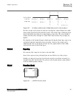
A disturbance report can be manually triggered from the local HMI, PCM600 or via
station bus (IEC 61850). When the trigger is activated, the manual trigger signal is
generated. This feature is especially useful for testing. Refer to the operator's manual
for procedure.
Binary-signal trigger
M12155-169 v4
Any binary signal state (logic one or a logic zero) can be selected to generate a trigger
(
Triglevel
= Trig on 0/Trig on 1). When a binary signal is selected to generate a trigger
from a logic zero, the selected signal will not be listed in the indications list of the
disturbance report.
Analog-signal trigger
M12155-171 v6
All analog signals are available for trigger purposes, no matter if they are recorded in
the disturbance recorder or not. The settings are
OverTrigOp
,
UnderTrigOp
,
OverTrigLe
and
UnderTrigLe
.
The check of the trigger condition is based on peak-to-peak values. When this is found,
the absolute average value of these two peak values is calculated. If the average value
is above the threshold level for an overvoltage or overcurrent trigger, this trigger is
indicated with a greater than (>) sign with the user-defined name.
If the average value is below the set threshold level for an undervoltage or undercurrent
trigger, this trigger is indicated with a less than (<) sign with its name. The procedure is
separately performed for each channel.
This method of checking the analog trigger conditions gives a function which is
insensitive to DC offset in the signal. The trip time for this initiation is typically in the
range of one cycle, 16 2/3 ms for a 60 Hz network.
All under/over trig signal information is available on the local HMI and PCM600.
16.6.8
Technical data
M12760-1 v10
Table 427:
DRPRDRE technical data
Function
Range or value
Accuracy
Pre-fault time
(0.05–9.90) s
-
Post-fault time
(0.1–10.0) s
-
Limit time
(0.5–10.0) s
-
Maximum number of recordings
100, first in - first out
-
Time tagging resolution
1 ms
See table
Maximum number of analog inputs
30 + 10 (ex internally
derived)
-
Table continues on next page
1MRK 511 408-UUS A
Section 16
Monitoring
Phasor measurement unit RES670 2.2 ANSI
579
Technical manual
Summary of Contents for Relion RES670
Page 1: ...RELION 670 SERIES Phasor measurement unit RES670 Version 2 2 ANSI Technical manual ...
Page 2: ......
Page 276: ...270 ...
Page 306: ...300 ...
Page 360: ...354 ...
Page 406: ...400 ...
Page 614: ...608 ...
Page 732: ...726 ...
Page 748: ...742 ...
Page 884: ...878 ...
Page 932: ...926 ...
Page 933: ...927 ...

