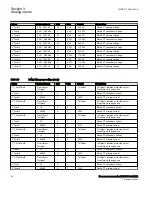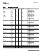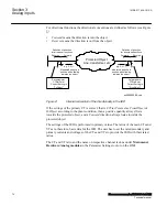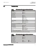
PID-4114-OUTPUTSIGNALS v5
Table 36:
LEDGEN Output signals
Name
Type
Description
NEWIND
BOOLEAN
New indication signal if any LED indication input is set
ACK
BOOLEAN
A pulse is provided when the LEDs are acknowledged
PID-1697-INPUTSIGNALS v18
Table 37:
GRP1_LED1 Input signals
Name
Type
Default
Description
HM1L01R
BOOLEAN
0
Red indication of LED1, local HMI alarm group 1
HM1L01Y
BOOLEAN
0
Yellow indication of LED1, local HMI alarm group 1
HM1L01G
BOOLEAN
0
Green indication of LED1, local HMI alarm group 1
5.3.4
Settings
PID-4114-SETTINGS v6
Table 38:
LEDGEN Non group settings (basic)
Name
Values (Range)
Unit
Step
Default
Description
Operation
Disabled
Enabled
-
-
Enabled
Operation Disabled/Enabled
tRestart
0.0 - 100.0
s
0.1
0.0
Defines the disturbance length
t_MaxTripDelay
0.1 - 100.0
s
0.1
1.0
Maximum time for the definition of a
disturbance
PID-1697-SETTINGS v18
Table 39:
GRP1_LED1 Non group settings (basic)
Name
Values (Range)
Unit
Step
Default
Description
SequenceType
Follow-S
Follow-F
LatchedAck-F-S
LatchedAck-S-F
LatchedColl-S
LatchedReset-S
-
-
Follow-S
Sequence type for LED 1, local HMI alarm
group 1
LabelOff
0 - 18
-
1
G1L01_OFF
Label string shown when LED 1, alarm group
1 is off
LabelRed
0 - 18
-
1
G1L01_RED
Label string shown when LED 1, alarm group
1 is red
LabelYellow
0 - 18
-
1
G1L01_YELLOW
Label string shown when LED 1, alarm group
1 is yellow
LabelGreen
0 - 18
-
1
G1L01_GREEN
Label string shown when LED 1, alarm group
1 is green
Section 5
1MRK 511 408-UUS A
Local Human-Machine-Interface LHMI
78
Phasor measurement unit RES670 2.2 ANSI
Technical manual
Summary of Contents for Relion RES670
Page 1: ...RELION 670 SERIES Phasor measurement unit RES670 Version 2 2 ANSI Technical manual ...
Page 2: ......
Page 276: ...270 ...
Page 306: ...300 ...
Page 360: ...354 ...
Page 406: ...400 ...
Page 614: ...608 ...
Page 732: ...726 ...
Page 748: ...742 ...
Page 884: ...878 ...
Page 932: ...926 ...
Page 933: ...927 ...

