


AngPP
ZPP
1
p1
p2
ZPP
2
p3
ZPP
3
Ohm/phase
R
jX
en07000009.vsd
IEC07000009 V2 EN
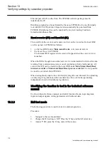
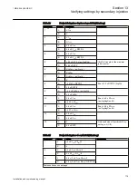
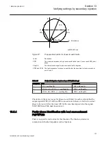
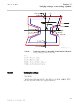
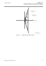
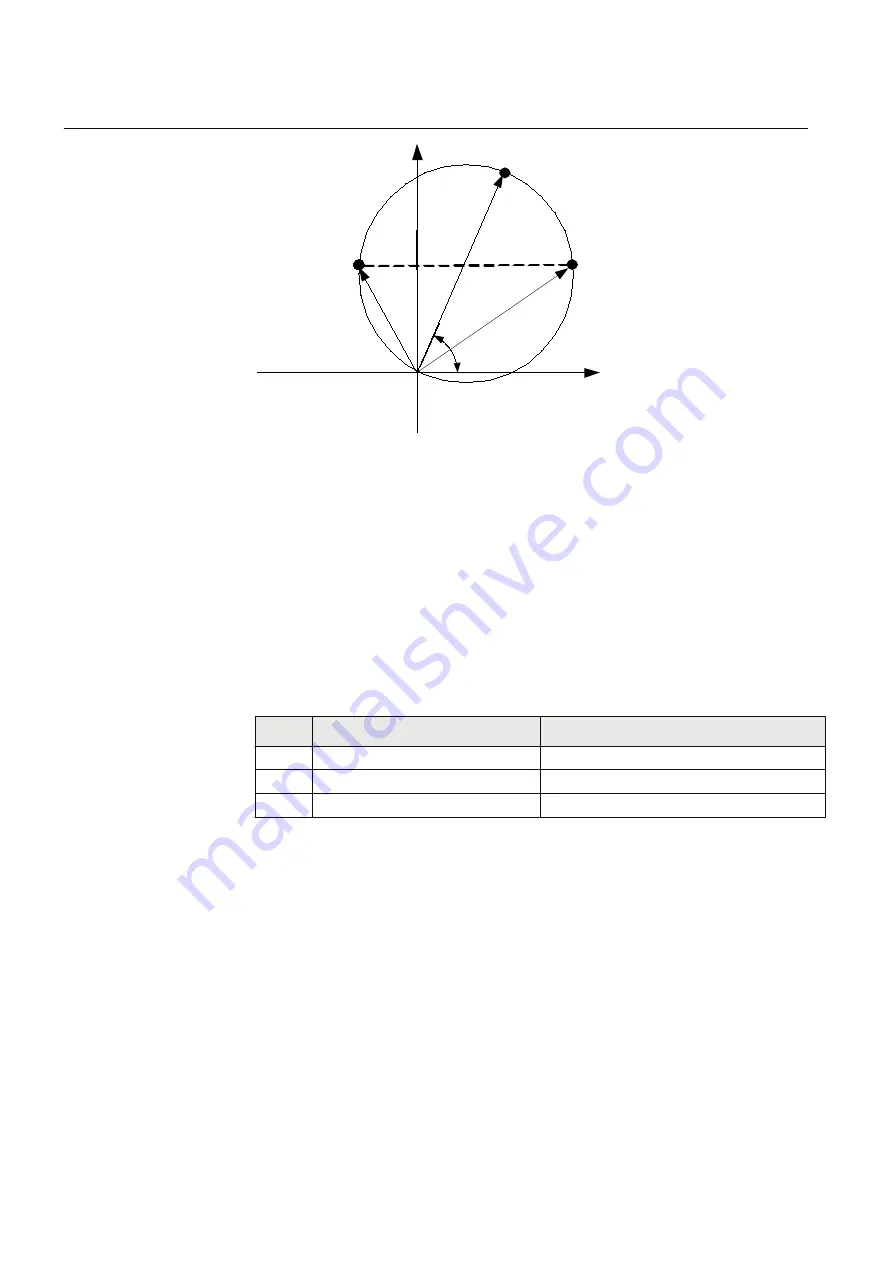
Figure 56:
Proposed test points for phase-to-phase fault
Label
Description
ZPP1
The measured impedance for phase-to-phase fault at point 1 (zone reach ZPP) ohm/
phase.
ZAngPP
The characteristic angel for phase-to-phase fault in degrees.
ZPP2 and ZPP3 The fault impedance for phase-to-phase fault at the boundary for the zone reach at
point 2 and 3.
Table 24:
Test points for phase-to-phase
Test
points
R
X
1
ZPP · cos(ZAngPP)
ZPP · sin(ZAngPP)
2
ZPP/2 + ΔR=ZPP/2 · (1 + cos(ZAngPP)) ZPP/2 · sin(ZAngPP)
3
ZPP/2 - ΔR = ZPP/2 · (1-cos(ZAngPP))
ZPP/ · sin(ZAngPP)
Change the magnitude and angle of phase-to-phase voltage to achieve impedances
at test points p1, p2 and p3. For each test point, observe that the output signals,
START, STLx and STPP are activated where x refers to the actual phase to be
tested. After the timer
tPP
for the actual zone has elapsed, also the signals TRIP,
TRPP and TRx shall be activated.
13.5.3.2
Phase-to-earth faults
For simplicity, the same test points as for phase-to-phase faults are proposed, but
considering new impedance values.
Section 13
1MRK 504 088-UEN C
Verifying settings by secondary injection
126
Installation and commissioning manual
Summary of Contents for RELION RET670
Page 1: ...Relion 670 series Transformer protection RET670 Installation and commissioning manual...
Page 2: ......
Page 16: ...10...
Page 24: ...18...
Page 26: ...20...
Page 28: ...22...
Page 82: ...76...
Page 88: ...82...
Page 94: ...88...
Page 104: ...98...
Page 110: ...104...
Page 210: ...204...
Page 230: ...224...
Page 239: ...233...


