


The voltage regulation algorithm then increases (for transformer
T2
) or
decreases (for transformer
T1
) the measured voltage by Udi and compares Ui
against the voltage deadband limits U1 and U2 for the purposes of voltage
regulation.
Ui UB Udi
=
+
EQUATION2090 V1 EN
(Equation 23)
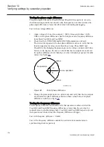
9.
To cause a tap change, the calculated value for circulating current voltage
adjustment must offset the injected quantity for bus voltage UB so that Ui is
outside the voltage deadband created by setting
UDeadband
. Expressed by
.
2
Udi U
UB
>
-
EQUATION2092 V1 EN
(Equation 24)
UB Uset
=
EQUATION2094 V1 EN
(Equation 25)
(for the purposes of this test procedure)
Therfore:
_
2
Ci Icc i Xi U
Uset
×
×
>
-
EQUATION2096 V1 EN
(Equation 26)
(
)
(
)
2
_
U
Uset
Icc i
Ci Xi
-
>
×
EQUATION2098 V1 EN
(Equation 27)
10. Using the settings for
USet
,
UDeadband
, C (Compensating factor) and
Xr2
(transformer short circuit impedance) calculate the magnitude of Icc
_i
necessary to cause a tap change command.
11. Inject current equal to
I2Base
for Transformer 1 and (
I2Base
- |Icc_
i
|) for
Transformer 2 so that the magnitude of calculated circulating current will
cause a raise command to be issued for Transformer 2 and a lower command
for Transformer 1. Magnitude and direction of circulating currents measured
for each transformer can be observed as service values on the local HMI and
raise/lower commands detected from the binary output mapped in the Signal
Matrix.
1MRK 504 088-UEN C
Section 13
Verifying settings by secondary injection
191
Installation and commissioning manual
Summary of Contents for RELION RET670
Page 1: ...Relion 670 series Transformer protection RET670 Installation and commissioning manual...
Page 2: ......
Page 16: ...10...
Page 24: ...18...
Page 26: ...20...
Page 28: ...22...
Page 82: ...76...
Page 88: ...82...
Page 94: ...88...
Page 104: ...98...
Page 110: ...104...
Page 210: ...204...
Page 230: ...224...
Page 239: ...233...


