

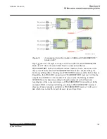
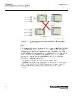


power system signal at the time it is applied to the PMU input. All of these
estimates must be compensated for PMU processing delays including analog
input filtering, sampling, and estimation group delay. If the sample time tags
are compensated for all input delays, the time tag of the sample in the middle
of the estimation window can be used for the phasor estimation (output) time
tag as long as the filtering coefficients are symmetrical across the filtering
window.
Note:
It is recommended to set this parameter on
MiddleSample
.
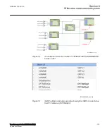
2. PHASORREPORT is the function block responsible for reporting the
synchrophasors. Each instance of PMUREPORT function block has 32 phasor
channels with the following setting parameters; where X is a number from 1 to 32:
•
PhasorXReport
: Enables/Disables the phasor channel X (reporting of
PhasorX) by choosing
On
/
Off
setting.
•
PhasorX
: The group selector for PhasorX. Here, the user can select the type
of reported synchrophasor from the phasor channel X as either a 3-phase
symmetrical component or a single-phase phasor. The options are as follows:
•
A
•
B
•
C
•
NEGSEQ
•
POSSEQ
•
ZEROSEQ
•
PhasorXUseFreqSrc
: Enables/Disables the contribution of Phasor channel X
in automatic frequency source selection by choosing
On
/
Off
setting. Each
voltage-connected preprocessor block delivers the frequency data, derived
from the analog input AC voltage values, to the respective voltage phasor
channel. Every phasor channel has a user-settable parameter
(
PhasorXUseFreqSrc
) to be used as a source of frequency data for reporting
to the PDC client. It is very important to set this parameter to
On
for the
voltage-connected phasor channels. There is an automatic frequency source
selection logic to ensure an uninterrupted reporting of the system frequency
to the PDC client. More information is available under the section
3. ANALOGREPORT is the function block responsible for reporting the analog
values. Each instance of ANALOGREPORT function block has 24 analog
channels with the following setting parameters; where X is a number from 1 to 24:
•
AnalogXRange
: This parameter defines a range between
-AnalogXRange
and
+AnalogXRange
for AnalogX value. The range will be used by the IED to
apply a proper scale factor to the AnalogX values when
Integer
format is
used. It refers to the 4-byte ANUNIT field of the configuration frames 1, 2
organization and the 8-byte ANSCALE field of the configuration frame 3
organization defined in IEEE C37.118.2 message format. The
AnalogXRange
value can be a number between
3277.0
and
10000000000
.
1MRK 504 163-UUS A
Section 6
Wide area measurement system
Transformer protection RET670 2.2 ANSI
133
Application manual
Summary of Contents for RELION RET670
Page 1: ...RELION 670 SERIES Transformer protection RET670 Version 2 2 ANSI Application manual ...
Page 2: ......
Page 48: ...42 ...
Page 64: ...58 ...
Page 74: ...68 ...
Page 104: ...98 ...
Page 194: ...188 ...
Page 518: ...512 ...
Page 618: ...612 ...
Page 648: ...642 ...
Page 666: ...660 ...
Page 672: ...666 ...
Page 682: ...676 ...
Page 844: ...838 ...
Page 868: ...862 ...
Page 956: ...950 ...
Page 964: ...958 ...
Page 1004: ...998 ...
Page 1014: ...1008 ...
Page 1015: ...1009 ...


