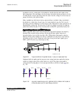
en06000621_ansi.vsd
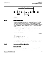
B
A1
A2
A3
D
B
D
A3
D
A2
D
A1
jX
11
I
A1
I
A2
I
A3
I
F
-jX
C
jX
1
jX
2
jX
3
F
X
ANSI06000621 V1 EN-US
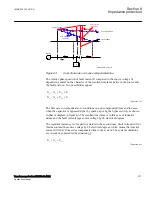
Figure 107:
Distance IED on adjacent
power lines are influenced by
the negative impedance
Normally the first zone of this protection must be delayed until the gap flashing has
taken place. If the delay is not acceptable, some directional comparison must also be
added to the protection of all adjacent power lines. As stated above, a good protection
system must be able to operate correctly both before and after gap flashing occurs.
Distance protection can be used, but careful studies must be made for each individual
case. The rationale described applies to both conventional spark gap and MOV
protected capacitors.
Special attention should be paid to selection of distance protection on shorter adjacent
power lines in cases of series capacitors located at the line end. In such case the
reactance of a short adjacent line may be lower than the capacitor reactance and
voltage inversion phenomenon may occur also on remote end of adjacent lines.
Distance protection of such line must have built-in functionality which applies
normally to protection of series compensated lines.
It usually takes a bit of a time before the spark gap flashes, and sometimes the fault
current will be of such a magnitude that there will not be any flashover and the
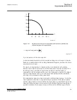
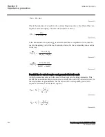
negative impedance will be sustained. If equation
11
11
<
<
+
C
S
X
X
X
X
EQUATION1898 V1 EN-US
(Equation 77)
in figure
, the fault current will have the same direction as when the capacitor is
bypassed. So, the directional measurement is correct but the impedance measured is
negative and if the characteristic crosses the origin shown in figure
operate. However, if there is a memory circuit designed so it covers the negative
impedance, a three phase fault can be successfully cleared by the distance protection.
As soon as the spark gap has flashed the situation for protection will be as for an
1MRK 504 163-UUS A
Section 8
Impedance protection
Transformer protection RET670 2.2 ANSI
231
Application manual
Summary of Contents for RELION RET670
Page 1: ...RELION 670 SERIES Transformer protection RET670 Version 2 2 ANSI Application manual ...
Page 2: ......
Page 48: ...42 ...
Page 64: ...58 ...
Page 74: ...68 ...
Page 104: ...98 ...
Page 194: ...188 ...
Page 518: ...512 ...
Page 618: ...612 ...
Page 648: ...642 ...
Page 666: ...660 ...
Page 672: ...666 ...
Page 682: ...676 ...
Page 844: ...838 ...
Page 868: ...862 ...
Page 956: ...950 ...
Page 964: ...958 ...
Page 1004: ...998 ...
Page 1014: ...1008 ...
Page 1015: ...1009 ...

