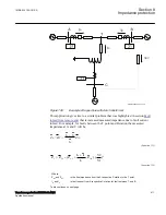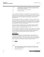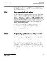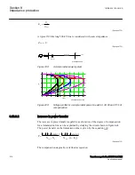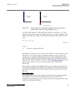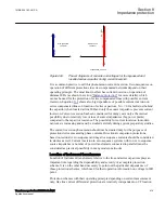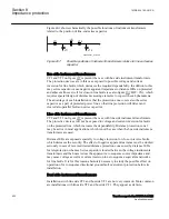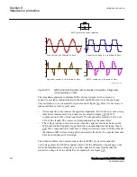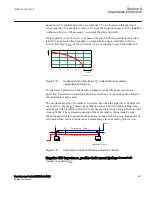
indicates the deepness of the network to which it will feel the influence of
series compensation through the effect of voltage inversion.
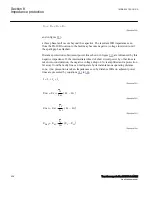
It is also obvious that the position of series capacitor on compensated line influences in
great extent the deepness of voltage inversion in adjacent system. Line impedance X
LF
between D bus and the fault becomes equal to zero, if the capacitor is installed near the
bus and the fault appears just behind the capacitor. This may cause the phenomenon of
voltage inversion to be expanded very deep into the adjacent network, especially if on
one hand the compensated line is very long with high degree of compensation, and the
adjacent lines are, on the other hand, relatively short.
Extensive system studies are necessary before final decision is made on
implementation and location of series capacitors in network. It requires to correctly
estimate their influence on performances of (especially) existing distance IEDs. It is
possible that the costs for number of protective devices, which should be replaced by
more appropriate ones due to the effect of applied series compensation, influences the
future position of series capacitors in power network.
Possibilities for voltage inversion at remote buses should not be studied for short
circuits with zero fault resistance only. It is necessary to consider cases with higher
fault resistances, for which spark gaps or MOVs on series capacitors will not conduct
at all. At the same time this kind of investigation must consider also the maximum
sensitivity and possible resistive reach of distance protection devices, which on the
other hand simplifies the problem.
Application of MOVs as non-linear elements for capacitor overvoltage protection
makes simple calculations often impossible. Different kinds of transient or dynamic
network simulations are in such cases unavoidable.
8.13.3.5
Distance protection
GUID-B8441469-8B23-494F-9BA8-D6A88DB2DC38 v2
Distance protection due to its basic characteristics, is the most used protection principle
on series compensated and adjacent lines worldwide. It has at the same time caused a
lot of challenges to protection society, especially when it comes to directional
measurement and transient overreach.
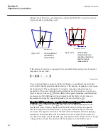
Distance IED in fact does not measure impedance or quotient between line current and
voltage. Quantity 1= Operating quantity - Restrain quantity Quantity 2= Polarizing
quantity. Typically Operating quantity is the replica impedance drop. Restraining
quantity is the system voltage Polarizing quantity shapes the characteristics in different
way and is not discussed here.
Distance IEDs comprise in their replica impedance only the replicas of line inductance
and resistance, but they do not comprise any replica of series capacitor on the protected
line and its protection circuits (spark gap and or MOV). This way they form wrong
picture of the protected line and all “solutions” related to distance protection of series
1MRK 504 163-UUS A
Section 8
Impedance protection
Transformer protection RET670 2.2 ANSI
425
Application manual
Summary of Contents for RELION RET670
Page 1: ...RELION 670 SERIES Transformer protection RET670 Version 2 2 ANSI Application manual ...
Page 2: ......
Page 48: ...42 ...
Page 64: ...58 ...
Page 74: ...68 ...
Page 104: ...98 ...
Page 194: ...188 ...
Page 518: ...512 ...
Page 618: ...612 ...
Page 648: ...642 ...
Page 666: ...660 ...
Page 672: ...666 ...
Page 682: ...676 ...
Page 844: ...838 ...
Page 868: ...862 ...
Page 956: ...950 ...
Page 964: ...958 ...
Page 1004: ...998 ...
Page 1014: ...1008 ...
Page 1015: ...1009 ...

